From time to time customers contact us who have bought a cooled CMOS camera, because they are not satisfied with their image results. They have been working with an uncooled DSLR camera or even a cooled CCD camera and compare the old images with what their new QHY delivers. So we often hear:
My images show way too much noise and hardly any signal from the subject". And many new astrophotographers (or those used to old technology) write to us: "My old images, taken with my DSLR, show much more of the object, even though the new camera is cooled and is supposed to be much more sensitive.
If that were the case, it would be really bad! That's why we want to take a look at CMOS technology here and give you a few hints on how you can dramatically improve your image results, because CMOS sensors in cooled cameras behave differently than CMOS sensors in a DSLR or even CCD cameras.
Everything was better in the past, they say - or let's rather say: everything was different in the past. With the older CCD technology, one had more little work with setting parameters for an exposure.
Was für CCD-Kameras galt, gilt heute nicht mehr!
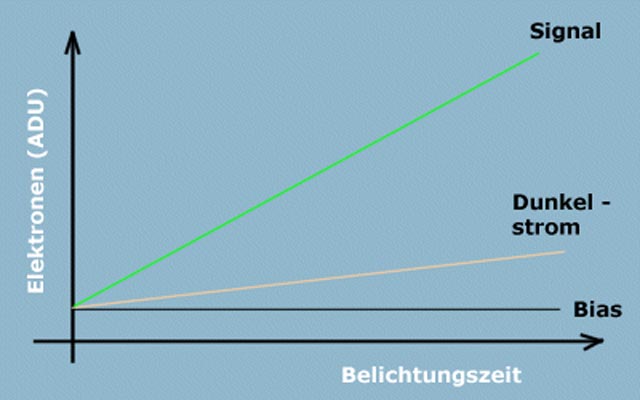
Back in those days, it was only a matter of connecting the camera to the computer, switching on the cooling (cool as low as possible), selecting the exposure time (expose as long as possible) and then saving the finished raw image. Nothing more was necessary, so everything was relatively easy. For image processing, just subtract a dark and a flat and adjust the tone curve a little in Photoshop. But CCDs do not behave the same as CMOS sensors, the sensors differ considerably in their technology and thus also in the settings for image capture (read our article on this subject, coming soon: CCD versus CMOS).
Das Gain
Gain is equal to amplification; in CMOS technology it means electronic image amplification. The gain is directly comparable to setting the ISO in a DSLR. Here there is the standard choice starting at ISO 100 up to ISO 6400 and with modern cameras far beyond.
The gain setting is one of the most important parameters for CMOS sensors. But beware: the correct choice of GAIN depends on the sensor type and thus on the camera in which the sensor is installed. The manufacturers usually only provide a so-called unity gain value, which is a good starting value for your shots. It is important to note that with the latest CMOS sensors, this should not be confused with the switching point between high and low read noise. With the advancements in CMOS technology, even at the lowest gain settings, the new 16-bit CMOS cameras exceed the requirements for the Unity GAIN setting (less than 1e/ADU).
At the end of this article you will find a table with unity gain settings for common QHY camera models. Later, as your expertise grows, you should optimize the GAIN setting for your needs, your local sky quality, and your standard exposure times. But keep in mind that changes in GAIN settings will also affect changes in other output parameters. The curves of the corresponding camera models show how these look.


The Unity Gain is the setting where Readout Noise changes from a lower to a higher value.
If you raise the ISO of a DSLR or a mirrorless camera from 100 to 800 or 1600 to get a brighter image with otherwise identical parameters (aperture, exposure time), you have to raise the gain on a cooled CMOS camera accordingly.
A GAIN of 1 or 0 is the minimum setting specified by the manufacturers and is comparable to an ISO setting of 6 to 12 on a DSLR. With this setting you could take pictures in bright sunshine.
ISO of a DSLR and GAIN of a CMOS camera have the same effect: when shooting with a very low GAIN, you have to expose for a very long time to get any signal at all from your subject. Tracking, sky quality etc. must be suitable or remain constant during the exposure time.
However, the noise components produced by the CMOS sensor and the sensor electronics (e.g. dark current) are constant! At low GAIN - when there is hardly any signal in the image - your raw images will therefore be very noisy and the signal of the subject will hardly stand out from the noise. When a very low GAIN value is chosen, the so-called full well capacity is also at its highest - and with it the image dynamics. Full well indicates how much charge (light photons) a pixel can collect before it is "full" and thus goes into overexposure with brighter stars. All the brightness that is collected has to be squeezed into the 16bit dynamic range afterwards, where the collected data is stored. (Of course, for this to happen, it must be recorded and stored in 16 bits!) A low GAIN therefore means a high dynamic range, but also longer exposure times and thus greater demands on the constancy of the observation conditions, and a poorer ratio of signal to sensor noise and dark current.
If you set the GAIN value too high for a better signal-to-noise ratio, the image dynamics will be reduced. Stars and bright objects such as the center of the Orion Nebula go into saturation, they will be overexposed and the central area of the nebula "burns out", i.e. there are no more shades of grey or colour, everything is white and overexposed.
Thus, the GAIN can be used to optimally adapt the image acquisition to your observation conditions. The faster your telescope is, the lower the GAIN can be set. Or you can use a shorter exposure time with a higher GAIN. The quality of "your" sky is also important: the darker the longer you can expose. With brighter skies, stack more frames to improve the signal-to-noise ratio.
By the way, the settings of GAIN and OFFSET can be found and adjusted in the ASCOM camera driver.
An example for better understanding:
The faster an optic is, the more the GAIN can be reduced for the same exposure time (compared to a slower telescope or smaller aperture)! In other words: with a faster optic, the exposure time can be shortened for the same GAIN.
If the GAIN value is increased with an average "fast telescope" (which, unlike a telephoto lens, has a fixed aperture or light intensity), the exposure time can be shorter.
-> This always refers to the background ADU and the brightest areas in the image.
There is more than one way to get the maximum of the night. The result is influenced by the number of exposures, the SNR in the stack, better seeing values through shorter exposure times, ...
After the exposure, the background in the image should not be above 10% saturation of 16Bit.
16Bit are 0-65535 tone values and 10% are around 6553 tone values (if you measure the ADU).
Also, the brightest areas of the image should not be overexposed (much)!
The centre of the brightest stars provides a good indication of whether it is not yet overexposed (or only very slightly). With more experience in image processing, this will become clearer, but it can be used as a basis.
The offset
However, there is a second important value to be determined for the optimisation of your CMOS raw images and that is the so-called OFFSET. The OFFSET shifts the histogram (the tone value curve) on the horizontal axis after the analogue-digital conversion.
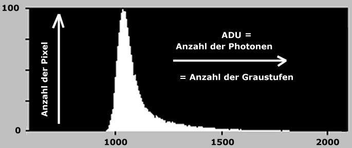
The histogram shows the brightness distribution of your raw image after the analogue-digital conversion. The horizontal axis shows the distribution of the grey values and the vertical axis shows the number of pixels and thus the corresponding brightness.
The offset corresponds to the gamma correction of the image and should be set so that in the end a value of at least 300 ADU remains for the background. This is checked on the exposed image after subtracting the correction images.
What is ADU?
Detailed information about the histogram and ADU (Analogue Digital Unit) can be found here(in German)
http://www.sbig.de/universitaet/glossar-htm/histogramm.htm
http://www.sbig.de/universitaet/glossar-htm/adu.htm
The maximum AD conversion is 16 bits, which corresponds to 65 535 grey levels between black (left in the histogram) and white (right in the histogram). With a 14 bit AD conversion, only 16 384 grey levels are represented; with a 12 bit AD conversion only 4096 grey levels. These grey levels are also called ADUs. With decreasing AD conversion, their histogram is thus compressed, so that the difference in the represented grey levels between black (sky background) and white (brightest stars) becomes significantly smaller.
The picture shows the ADU values of two measured objects for clarification. In the photo, the small planet 1991 RG7 (approx. 18th magnitude) is marked in the small square, and a reference star of the 12th magnitude is marked in the large square.

In the evaluation, the minor planet corresponds to number 1, the reference star to number 2. You can clearly see the difference in the two ADU values between 1157 and 39565. It is also logical that in the table the last column with the value for S/N (the signal-to-noise ratio) shows similar ratios. Of course, the small planet has a much worse S/N ratio than the brighter star.
However, let's stay with an AD conversion of 16 bits (0 to 65 535 ADU). After exposure, the background should not exceed 10% of the saturation, which is about 6500 ADU. Also, the brightest areas (bright stars) should not be overexposed yet.
Now, when taking deep sky images, you will always be on the left-hand side of the histogram and your (faint) object of observation will hardly stand out from the sky background. To prevent the signal from disappearing in the negative area of the histogram, the OFFSET shifts the tone curve to the right. The OFFSET should be set so that at the end the sky background remains at a value of about 300 ADU. If the OFFSET is set too low, so-called "dark patches" appear in the sky background, which are very difficult to correct in image processing - apart from the fact that they naturally lose object signal.
Determing the Correct OFFSET in Two Steps
You need to take two images to determine the OFFSET. These are a so-called bias and a dark frame.
To do this, first select an appropriate gain - either from your own experience or according to the output values that QHY CCD specifies for the camera model.
- The bias frame detects the electronic noise systematically generated by the AD converter for each pixel. The exposure is recorded with the shortest possible exposure time with the shutter closed (telescope aperture covered) so that no light hits the sensor. The resulting image ideally contains only the noise generated by the readout process itself for each individual pixel - it is referred to as read noise or readout noise.
The bias frame MUST be taken with the same settings for GAIN, sensor temperature, binning and readout mode as the later raw images. Take 30 to 50 bias frames, stack and average them (e.g. DeepSkyStacker). Now you have to measure the signal of the background noise with an image processing software (Fitswork, Pixinsight, Maxim DL). The value should be around 850 ADU. Start with the preset OFFSET value in the camera driver (e.g. 55 for the QHY 268M or 60 for the QHY 600M).
2. Now a dark frame is captured. As with the bias frame, the GAIN, sensor temperature and readout mode must be the same as the images which are later taken of the deep sky objects. The dark frame is also exposed with the camera shutter closed or the telescope aperture covered.For each pixel, tt measures the respective ADU value, which is generated without light incidence only by thermal kinetic energy within the sensor and the camera electronics. This is the dark current noise (Dark Noise).
Now you have to measure the value of the noise again. The value should be about the same as the value of the bias frame, but never lower, otherwise the OFFSET must be increased. This is done either in the ASCOM driver of the camera or in the recording software.
For more accurate results, take several dark images again, which you stack and average.
These two calibrated correction images are essential for later image processing!
From now on, the following happens: If you now take an image of an astronomical object and download it from the camera, the data contains the signals of the camera (the noise) and the sky (the object).
Now, when bias and dark frame are subtracted, the pure signal of your observing object remains, bias and dark current noise are eliminated. By the way, even better than a normal bias is a flat dark.
What should not happen is that the sky background drops below 300 ADU. Otherwise, with 16 bits, the value is too close to zero! Then the OFFSET value must be raised slightly. Around 800 ADU after calibration is OK and corresponds to just under 1 % of the 16 bit tonal range - there is no loss of object signal.
So with the offset you shift the gamma value away from zero, but only so far that the values of darks and bias are about the same.
In addition, pedestal values can be added, often a value around 200 is preset.
By the way, the dark image not only corrects the noise, but also removes all missing pixels of the sensor (hot and cool pixels, see also here for more details). If there are still hot pixels left in the final image after stacking, you should take new darks - and remember that light must not be allowed to enter anywhere, not even at the focuser, the filter drawer or the like. If everything has been subtracted correctly, every hotpixel should have disappeared!
If you notice a pattern in the background, it often has to do with the bias and with a too small or inappropriate offset between the exposures during dithering! A solution is a larger pixel offset between the shots, a flat dark instead of a normal bias (see below) and checking whether the bias was applied correctly in the stack.
Hints:
- If GAIN, OFFSET or Readout Mode are changed, the calibration images - Bias and Darkframe - MUST be retaken.
- If you use bias frames, the image processing software MUST "know" that the dark frame also contains the bias value, otherwise it will subtract twice and result in increased noise or negative values
Tabel with Unity Gain values for some QHY cameras
| Camera | Unity Gain | Switch Point High Gain / Low Gain Conversion |
|---|---|---|
| QHY 600 M/C | 25 at Extended Full Well | Photography Mode: 26 / High Gain Mode: 56 |
| QHY 268 M/C | 30 at Extended Full Well | Photography Mode: 26 / High Gain Mode: 56 |
| QHY 183 M/C | 10 | |
| QHY 163 M/C | 120 | |
| QHY 533 M/C | 68 | 60 |
| QHY 367C | 2800 | |
| QHY 247 C | 2200 | |
| QHY 128C | 3300 | |
| QHY 168C | 10 | |
| QHY 410C | 90 (Low Gain) 40 (High Gain) | |
| QHY 294 M/C Pro | 1600 (11 Mp Mode) 2600 (47 Mp Mode) | 11 MP Mode: 1600 |
| QHY 174 GPS | 17 | |
| QHY 550P | 85 |
You can find the Unity Gain for further camera models on the QHY Website.
(1)Unity-Gain Value: For example, the latest CMOS sensors clearly show the switching point between "High Gain Conversion" and "Low Gain Conversion." Beyond this GAIN setting, the read noise (e-) drops significantly, and the dynamic range increases due to the lower noise ratio. This switching point between HGC and LGC is not the Unity Gain, where 1 electron per ADU hits the sensor (1e=1ADU).
Wolfgang Paech + Christoph Kaltseis im April 2022
About the authors:

Christoph Kaltseis is not only an Adobe Photoshop specialist and as Nikon Professional touring for Nikon, but also an experienced astrophotographer. He is one of the founders of the Central European DeepSky Imaging Conference (www.cedic.at), which is held every two years in Linz since 2009.
In addition to his various projects, Christoph has developed an innovative image sharpening process called APF-R (Absolute Point of Focus)in recent years. The procedure is not always the same, but is adapted to the combination of lens and camera. Therefore, a flexible method was necessary to achieve the desired results.
In his career as an astrophotographer Christoph has also created several APODs (NASA Astronomy Picture of the Day), e.g. the APF-R-processed image of the M33 Galaxy or the Heart of the Orion Nebula (M42).

Wolfgang Paech has been practicing astronomy for more than 50 years. In addition to his many experiences with observatory domes of all kinds, his core areas are the Sun and the Moon. On the german Website www.chamaeleon-observatory-onjala.de you will find a complete moon atlas, recorded with his standard technique. But even in terms of Deep-Sky and Planetary imaging, as a veteran astrophotographer for many years, nobody can fool him.
The 50+ years of amateur astronomy with many other areas, such as the restoration of historical amateur telescopes, polar light trips and much more are prepared on his private german website at www.astrotech-hannover.de.