New f/3 Ultra-Highspeed (Ultra-Narrowband) Filter Category
During the last couple of months after introducing our new CMOS-optimized filter families, we have received lots of positive feedback from our customers.
However, there was an increasing number of reports and long discussions about low signal, halo strength and so on, which showed more and more, that the complexity of this topic needs a really detailed explanation. Especially when going to the physical limits, like with our Ultra-Narrowband (UNB) filters, there is no standard solution for every user with different telescopes, sky and weather conditions
This situation was intensified because the f/2 Ultra-Highspeed filter category especially needs a more selective categorization, in order to select filters with the correct PRESHIFT, to comply with the f/ratio and the amount of obstruction of the respective telescope optics.
Until some weeks ago most users received filters which worked very well for them, while some others received the same filters – but they worked poorly on their scope. It took us some time to prepare the necessary insight and knowledge base on how to select filters matched for the many different f/ratios, as well as the different levels of secondary obstruction in case of catadioptrics and newtonians.
Kindly take the time to follow through with us and learn what has not been explained anywhere decently until now:
Preshift – what is it ?

Whitepaper: Narrowband Filters on Astronomical Telescopes
The theory explained in short
When working with f/2 (to a lesser degree also with f/3 and longer focal lengths), incoming angles of light will cross any filter with an inclination from 0° to a maximum of 14° with f/2 telescope optics. This requires the bandpass of Highspeed-dedicated Narrowband filters to be red-shifted by 1 nm to 2,5 nm, depending on the optical parameters of the telescope. Most filter suppliers simply do not preshift their filters peak wavelength at all and customers always receive a filter that is produced "straight on band". This will work well for most telescopes as long as the filter FWHM stays wide and the f/ratio stays well above f/3.4 and only if the telescope optics has zero central-obstruction. But downwards of < f/4 and in conjunction with increasing obstruction of faster optical telescopes, nothing is "on band" anymore, since the transmitted wavefront experiences an ever increasing "blue-shift" – as mentioned, depending on the f/ratio and the amount of obstruction. Without compensating this inevitable blue-shift by a suitable red-preshift, a 95% peak-transmission filter may mutate into a 30% transmission filter. For this reason we always did differentiate between regular narrowbands without preshift and highspeed filters featuring a preshift, in order to provide maximum filter transmission for the wide range of telescope f/ratios.
So far filter manufacturers did not offer information on the necessity of preshifting narrowband filters at all (very few do offer preshifted filters "on special demand" – at high cost). From a manufacturers perspective this might be somewhat understandable as it requires stocking a multitude of different filter sizes and different filter families for different telescope optics, each filter category redshifted differently by a closely defined degree. And in order to make things even more difficult, even temperature shift needs to be considered to a minor degree. For instance, under actual imaging conditions in a winter night at - 20°C, the same filter will have a slightly different shifted transmission window than when used in the lab at +20°C. This will remain insignificant for long focal length optics but becomes increasingly relevant with faster optics. For this reason, below we do show the different temperature filter shift behaviour for temperature ranges from -20°C to +20°C in three separate graphs.
Now finally, all of the above is explained in necessary detail and with explaining graphs in a 24 page whitepaper
If you want to dig into the subject of narrowband filter shift, we ask you to please study it carefully.
[br]
The problem identified
Example: H-alpha 3.5nm Ultra-Narrowband/Highspeed Filter Selector Graph
Usually for O III (and S II) a signal strength similar to H-alpha is expected/hoped for, but this is limited by physics. Equalizing signal strength of narrowband O III / S II data to those gained at H-alpha always requires longer or more exposures than in H-alpha, owing to much less energy supplied by O III and S II nebula emission lines. Hard stretching of insufficient depth of data will certainly bring out halos. It is the main reason why there is seldom any halo complaint for H-alpha-filters, compared to O III and S II filters. This fact led us to not listen closely enough when feedback occurred concerning insufficient signal – mostly concerning the Highspeed-Version of Ultra-Narrowband filters used at fast optics.
Example: OIII 4nm Ultra-Narrowband/Highspeed Filter Selector Graph
Actually we were convinced to be already doing good to the astro community by offering preshifted filters at all, in the form of a f/2 highspeed filter category, while keeping prices for such small and dedicated production runs well within affordable limits. For many years we offered f/2 highspeed-filters that work very well, while having slightly wider passbands than the current 6.5 nm f/2 Highspeed filters. Both our current 6.5 nm CMOS-optimized highspeed filters as well as the former CCD-highspeed filters have been produced with a preshift to serve a telescope f-range from f/3.4 down to f/1.8. This works well for filter FWHM-passbands as narrow as 6.5 nm (see the detailed explanations in the whitepaper linked above), but it was not decently explained until now about how to select between regular narrowband versus highspeed-narrowband filters – which has caused difficulties for users to differentiate between the two, with some users ending up with a filter providing less signal than expected. For this reason the two different 6.5nm Narrowband/Highspeed filter categories have also been included in our selector below.
But what still does work well with only two filter categories at FWHM of 6.5 nm (Narrowband and f/2 Highspeed) we had to learn does not work as well with FWHM 3.5 nm and 4 nm filters. At such even narrower filter passbands as 3.5 and 4 nm, the two so far available filter families of Ultra-Narrowbands and f/2 Ultra-Highspeeds did not make it possible to match filters perfectly to the users telescope(s) in the f/range from f/3.4 down to f/2.3. So in case your telescope optics does work inside that f-range of faster than f/3.4, respectively slower than f/2.3, chances are that you were supplied with the wrong 3.5/4 nm filter preshift and rightfully report about low filter transmission. For all other f/ratios the decision between Ultra-Narrowband or f/2 Ultra-Highspeed does work well and here we got only very few feedback on signal loss.
Example: SII 4nm Ultra-Narrowband/Highspeed Filter Selector Graph
It took us some time to find that the cause of reports concerning low signal and halos does come almost entirely from people having bought an f/2 declared Ultra-Highspeed filter – but using it in the range of f/2.3 to f/3.4. Or people having bought a 3.5/4 nm Ultra-Narrowband filter but using it with optics below f/3.4.
This situation had caused us to stop filter deliveries in recent weeks and use the time to redo our filter categorization on the 3.5/4 nm Ultra-Narrowband / Ultra-Highspeed Filters into three distinctive categories
- Changed working range:
3.5/4nm f/2 Ultra-Highspeed, with preshift exclusively for telescope optics faster than f/2.3 (formerly declared from f/3.4 to f/1.8)
- NEW:
3.5/4nm f/3 Ultra-Highspeed, with preshift exclusively for telescope optics ranging from f/2.3 to f/3.4
- Unchanged:
3.5/4nm Ultra-Narrowband, without preshift – for telescope optics slower than f/3.4
The selector tool shown below will make it easy for you or your dealer to identify the most suitable filter category for your telescope or your range of telescopes. It quickly becomes obvious that choosing filters in the wider passband of 6.5 nm will cover a wider range of optics and be more affordable at the same time. These are very good "bread&butter"-filters.
However, there is a reason to decide for one of the (now) three Ultra-Narrowband/Highspeed categories. Mostly when you must work under bright skies in or in the vincinity of a city or other heavy light pollution. In general a sky brightness above Bortle 7 absolutely justifies to use a 3.5/4 nm filter that has ~ 1.4x better contrast than the otherwise similar 6.5 nm filter.
Baader Narrowband-/Highspeed Filter Selector
People with f/3.4 down to f/2.3 telescopes that have problems with obtaining decent signal are invited to contact us so it can be decided if a refund or exchange is suitable, or if there are other solutions/advice at hand.
Baader Narrowband-/Highspeed Filter Selector
To make it easy for you in the future to decide which kind of Highspeed (or Narrowband) filter you need for your telescope, please check the new selector tool that provides you the correct individual graph based on your entries. In general please note that there are multiple factors to take into account when selecting a (Ultra-)Narrowband/Highspeed filter:
- The aperture ratio (f/#) as well as the desired FWHM (6.5nm or 3.5/4nm)
- Vignetting (central-obstruction in %) of the optical system greatly influences filter blue shift and needs to be put into the graph, in order to find the best suited filter
- Temperature shift: whatever you measure in a warm lab at 20°C, at -20°C it will shift into blue by about 0.4 nm to a maximum of ~1 nm. So the average temperature of your observation site ought to be taken into account, mostly when selecting (Ultra-)Narrowband/Highspeed filters
Thank you for reading and for your consideration.
If you notice that the edges of your image(s) are not sharp then image tilt may be present in your system. Image tilt is caused when the sensor is not perpendicular to the light path. The cause(s) of image tilt can be many and can include flattener/corrector lenses, tilted focuser drawtube, extension adaptors, camera angle adjusters as well as inherent camera sensor tilt in the camera body itself. Being able to correct for this image plane tilt is important and essential to get perfect focused sharp star images across the field of view.
Baader Planetarium currently offer three accessories - their "Tilter family" - that can help compensate for image plane tilt.
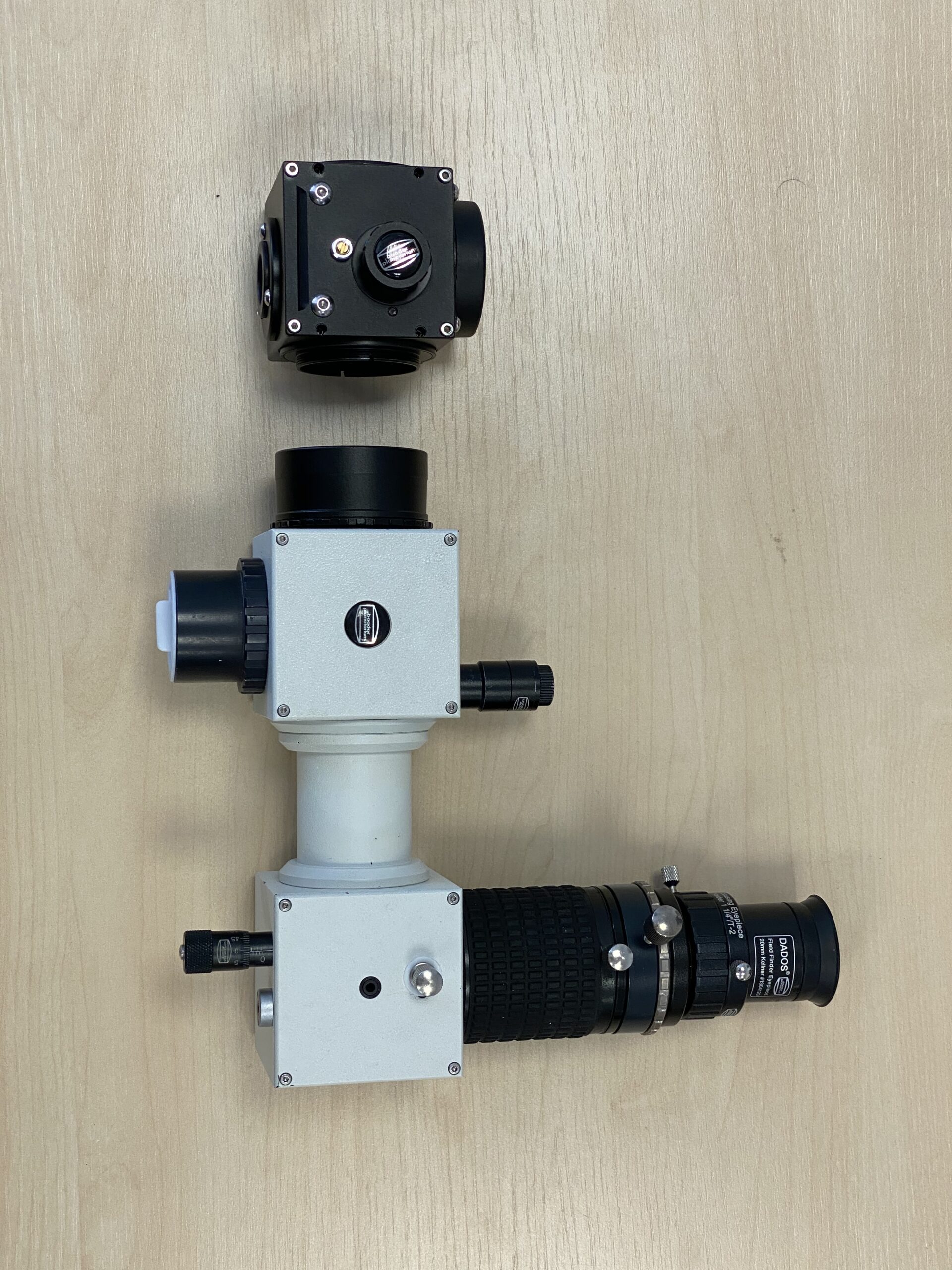
Example set up: UFC Base Chamber (left) with UFC Tilter (middle) and S70 T-2 Telescope-side adapter (right)
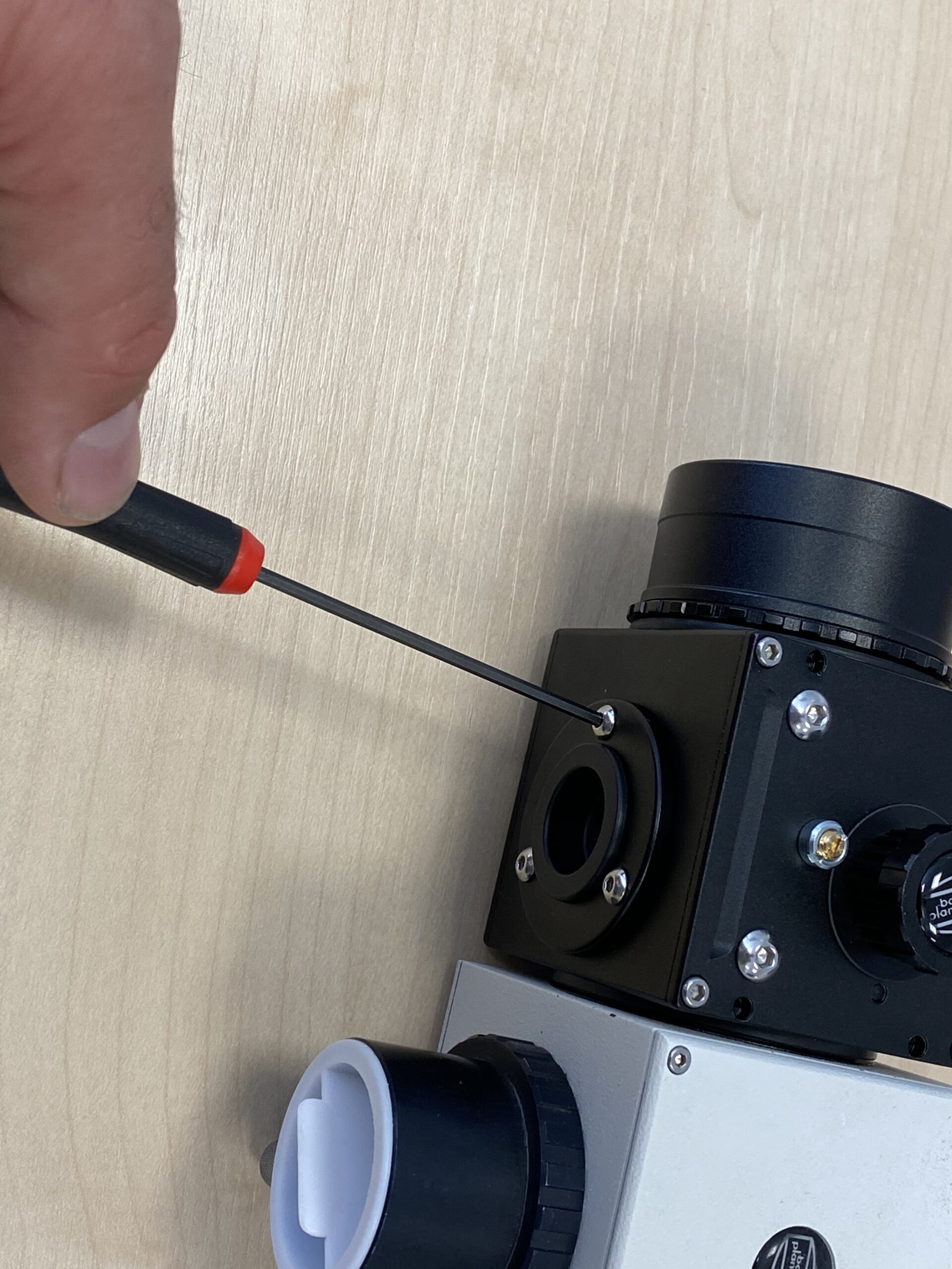
UFC Tilter: Click on the image to see the Tilter in action and how the adjustment are made.
[product sku="2459146"]: an S70 dovetail accessory that fits on the telescope side of the UFC and it is compatible with the entire Baader UFC system. The unit allows an adjustment tilt shift of the UFC Base (and an attached camera) of up to 1° to compensate for misalignments in the image field. The Tilter is only 9.75-10.50 mm in optical length depending on amount of tilt adjustment made.The wide range of telescope- and camera-side adaptors allow the UFC-Tilter combination to be used on a huge range of telescopes which have sufficient back focus from small refractors to the Celestron RASA36 and even larger instruments including PlaneWave telescopes and also a large number of cameras from different manufacturers.
To find out more about the UFC Tilter read Part 10 of our UFC series of articles.
[br]
M68 Tilter: Click on the image to see the Tilter in action and how the adjustment are made
Example setup showing Baader M68 adapter + M68-Tilter + Nikon D810A
[product sku="2458170"]: is a new addition to the M68 (Zeiss) thread system of accessories which are used for sturdy connection of optical accessories and will result in no flexure under heavy equipment load. The M68 system allows you to mount heavy accessories (e.g. camera and filterwheel) in a rigid and stable fashion and without vignetting due to the large internal diameter, and with the inclusion of the M68 Tilter allows you to precisely adjust for any tilt in a simple and manner. The tilt mechanism, which is similar to that of the UFC Tilter and FCCT (below), is designed in such a way that if the M68 tilter is removed together with the camera and is replaced with another the adjustment is retained. The M68 Tilter is for use with the M68 system but it can be adapted to work with the popular smaller M42/M48 system - we will cover this in an article soon.
To find out more about the M68 Tilter and some examples of its use on a large aperture telescope with a heavy imaging camera and a DSLR read Christoph Kaltseis' interesting article: With the Baader M68 Tilter to perfect alignment.
[br]
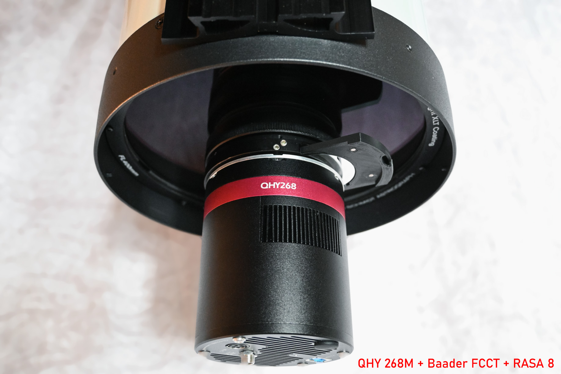
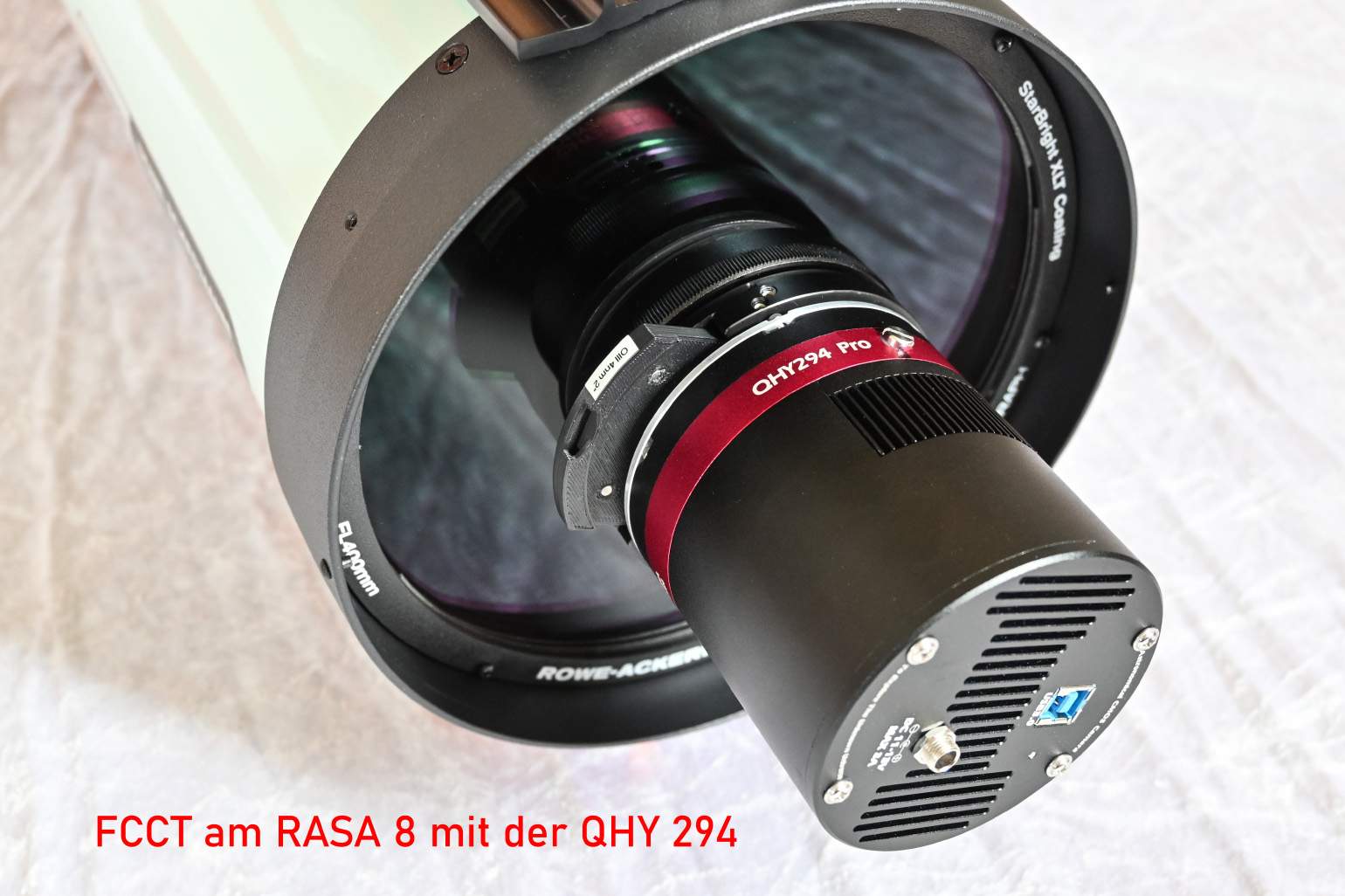
FCCT attached to the RASA8 with a QHY camera. The FCCTs are supplied with a long-handled hex-screewdriver for easy tilt adjustments
The two versions of the FCCT for different sized QHY camera bodies.
Filter Changer and Camera Tilter (FCCT): a new specially designed dedicated accessory for use with the Celestron RASA8 imaging telescope and a range of QHY cameras only.
Unlike the UFC and M68 Tilters, which are in themselves a tilt-adjuster only, the FCCT combines the functionality of a tilter with an integrated filter changer. The FCCT was born to address the fact that due to the small amount of back focus of the RASA8 a wide range of the the popular QHY cooled CMOS cameras could not, until the release of the FCCT, be used with a filter drawer to swap filters and allow you to easily correct for image plane tilt. The FCCT allows you to easily swap filters and to correct for image tilt without the need to remove the camera when adjustments are needed. Two versions of the FCCT are available and which one you need depends on your camera model:
-
- FCCT I for RASA 8" – suitable for QHY cameras with 77 mm diameter (e.g. QHY 174 / 163 / 183)
- FCCT II for RASA 8" – suitable for QHY cameras with 90 mm diameter (e.g. QHY 268 / 294)
A 3D printed filter holder: in this example it is the 36mm version. The two small silver "dots" are built-in Neodymium magnets to ensure that the filter drawer is always held in the same position and cannot fall out.
To accompany the FCCT for using filters there are three different versions of high quality 3D-printed filter holders, available separately (individually or in packs of 4) that accommodate unmounted filters with standard sizes of 31 mm and 36 mm and a new 47.4mm dimater size (Baader 2" mounted filter but without a cell). For the high-speed RASA8 telescope you can use the Baader LRGB CMOS Optimised filters and the Narrowband and Ultra Narrowband Highspeed H-Alpha, S-II and O-III filters which are all available singularly in the aforementioned 31/36/47.4mm sizes. An [product sku="2459075"] is available separately that allow the FCCT I to be converted to an FCCT II should you change or upgrade your camera.
To find out more about the FCCTI and II and how it is used with the RASA8 and QHY cameras you can read the detailed user guide and also an article on the RASA 8 with QHY Cameras and the FCCT.
Each of the three models in the Tilt family help correct for tilt but their application and usage are different. What they do share in common and is a major and important "practical feature" - that the fine tilt adjustment screws are located 120° apart on the outside edge meaning that they are easily accessible even with a camera attached. Other tilt adjusters have these on the camera-facing side meaning that they are often obstructed and require repeated repeated threading and unthreading of cameras and adaptors. With the Baader family of tilters, the whole "tilt adjustment operation" can be achieved without imaging train removal. Tilt adjustment is performed using three pairs of opposing set screws, on the tilter's outside edge, which independently move the inner tilt mechanics. These hex screws have tapered and hardened points that bear against a precision hardened ‘zero-clearance’ internal steel-counterpart. The direction that each set screw moves the tilter is shown with a helpful etched arrow next to each individual adjustment screw. You can read more on how to finely adjust tilt with the UFC-, M68- and FCCT-Tilters in an article here. All three Tilters are of all-metal construction and are made to very high precision in Germany.
[br] The table below gives you a "summary" of some of the specifications for the current tilter family.
| Specification |
UFC Tilter |
M68 Tilter |
FCCT I |
FCCT II |
| Weight |
0.08kg |
0.083kg |
0.15kg |
0.16kg |
| Path Length |
9.75-10.50mm |
9.50-10.25mm |
21.5mm (incl. 2x 0,5mm Spacer wich can be added) |
21.75mm (incl. 2x 0,5mm Spacer wich can be added) |
| Outside Diameter |
92mm |
92mm |
93mm |
93mm |
| Scope-side Adaptation |
Various: UFC Telescope-side Adaptors |
M68x1 (i; internal) |
Secured on RASA 8 lens group cell with coupling ring |
Secured on RASA 8 lens group cell with coupling ring |
| Camera-side Adaptation |
Various: UFC Camera-side Adaptors |
M68x1 (a; external) |
Secured to QHY camera faceplate after removal of ring dovetail |
Secured to QHY camera faceplate after removal of ring dovetail |
| Tilt |
0°-1° |
0°-1° |
0°-1° |
0°-1° |
| Accessory weight capacity |
5kg |
5kg |
2kg |
2kg |
| Filter usage |
With UFC and UFC Sliders |
With UFC and UFC Sliders |
With 3-D Printed 31/36/47.4mm Sliders |
With 3-D Printed 31/36/47.4mm Sliders |
[br]
The planets Saturn, Mars, Venus and Jupiter are making an appearance in our morning sky making a lovely photogenic celestial lineup. About an hour before sunrise you can see the magnificent ringed gas-giant planet, and second largest planet in our Solar System, Saturn towards the south east with our red coloured neighbour Mars sitting below and to the east of it. Venus is next in line shining brightly at magnitude ~4.2 and is exhibiting a gibbous phase and very low near the eastern horizon is the largest planet Jupiter. These planets will make their way to being evening objects later in the year becoming better positioned where they will be observable for longer. Our Moon is easily seen throughout most of each month so its a frequent and easier object for observation and/or imaging.
Simulated view of the mid-April morning sky about one hour before Sunrise. Venus dominates the planetary lineup low in the East-to-South East horizon.
Planetary observers are likely to own a number of eyepieces, changing between them to get differently magnified views of our Moon, the planets (and many deep sky objects). Owning multiple eyepieces comes with a few "associated issues". One is of course having to physically remove and safely store that current eyepuece, and then locate another eyepiece and insert it in your focuser and refocus if necessary. Its also important to think about where to store the (unused) eyepieces in the interim - on a table or in a box or storage case for example.
Wouldn't it be useful to have a device that holds a number of eyepieces you would most often use so switching between them is so much easier and more convenient? Enter the Baader Q-Turret Four Eyepiece Revolver.
[br]
The 1.25" Q-Turret 4-Eyepiece Revolver
Showing the compact size of the Q-turret
With the Q-Turret you can select up to four 1.25" eyepieces (or three eyepieces and a small imaging camera) you want to use at the telescope. The turret is designed to be used with low weight small eyepieces such as Plossls or similar (see below) rather than larger heavier optics. Next, place them in the Q-Turret's eyepiece holders and use the knurled locking screw on the side of each eyepiece holder to secure them in place. Insert and secure the turret's 1.25" nosepiece into your focuser drawtube and then revolve the turret to select which eyepiece you want to be in the telescope's light path. Its that simple. The unit features a simple but firm "click stop" so you know when an eyepiece reaches the correct position in the telescope's lightpath.
How to organise the eyepieces in the revolver is down to personal choice. For example you could organise eyepieces in structured way of decreasing focal length (increasing magnification) as you rotate the turret clockwise (or anticlockwise) from the initial lowest power eyepiece so that you know how the view will change.
Its small depth only adds ~38mm to the back focus
Baader Q-Turret with 3 eyepieces and imaging camera
The Q-Turret accessory is not a bulky accessory - it has a small form factor. It is quite compact and fits nicely in the palm of your hand measuring only 120mm in diameter (outside of barrel to outside of opposite barrel). The Q-turret is also not very long and adds only ~38mm to the path length (i.e. moves the eyepiece out by this amount) so can be used in a wide range of telescopes.
To keep the overall weight low and cost affordable, the turret is made of strong but durable plastic and as a result only adds just under 100g to the telescope.
The example set up shown in the image to the right consists of the Q-turret along with a Celestron’s 40mm E-Lux and 13mm Plossl, Baader Genuine Orthoscopic eyepiece and a Celestron Skyris planetary imaging camera where the overall weight of this visual/imaging setup comes in at just under 520g.
[br]
The Q-turret and Eyepiece and Barlow Package
In addition to the Q-Turret being available as a stand-alone accessory, it is also available as part of a complete visual eyepiece and barlow package: [product sku="2957000"]
This set comprises the following high quality components
This set is ideal for those who want a complete and versatile Lunar and planetary observing accessory package "out of the box". Let's look at the package contents in a little more detail.
[br]
Classic Eyepieces
Orthoscopic eyepieces are often the eyepiece of choice for many Lunar and planetary observers with their very high image quality and sharpness. The Baader Classic Ortho eyepieces are available in focal lengths of 6mm, 10mm and 18mm. One of the first things to notice is how light they are weighing in from just under 40g for the 6mm classic Ortho up to just over 90g for the 32mm Classic Plossl. Although their low weight may make you think their optical quality is low, they use the same glass and triplet element-plus-one plano-convex eye lens optical design as the old Orthoscopic eyepieces that were produced by Zeiss Jena - a good sign of high quality! In fact the Q-Turret and eyepiece set was reviewed by Sky and Telescope in their October 2013 issue and was selected as one of their Hot Products for 2014!
Simulated views of our Moon
The Classic Ortho eyepieces each have a 52° apparent field of view, with the 32mm Plossl having ever so slightly less at 50°. All of the range are parfocal meaning that when you switch between the different Classic eyepieces no, or very little, focus adjustment is needed. Each lens features sharp field stops, and to maximise light throughput and minimise internal reflections High-Transmission Multi-Coatings (HT-MC) are applied on all the glass-to-air surfaces. The eyepiece bodies also have blackened interiors for stray light suppression and maximum contrast. The 1.25" eyepiece barrels are threaded to accept standard 1.25" filters to help with Lunar and planetary observation (e.g. 1.25" Six Colour Filter Set - Moon and Planetary). All four eyepieces are supplied with rubber removable winged eyecups (also available separately - in case of the need for a spare or a replacement: [product sku="2454652"]) which are ideal to help keep stray light out (e.g. Moon glow or a neighbours outside light) when viewing which also helps improve the view. The winged eyecups are easily be folded back leaving a flat surface which may be suitable for some (e.g. glasses wearers).
The magnification and field of view you will get with these eyepieces all depends on the telescope being used. Schmidt-Cassegrain telescopes are good all-rounders for those wanting to view and image the Moon and planets as well as deep sky objects too. The image (right) shows the simulated field of view and magnification you will get (using Stellarium) with our Moon, a popular celestial target, with the 32mm Classic Plossl (top left) and clockwise the 18mm, 10mm and 6mm Classic Ortho eyepieces.
Below is a table with some more details about these Classic eyepieces.
|
Focal length (mm)
|
Optical design |
Barrel |
Lens elements / groups |
Apparent field of view |
Parfocal |
EyeRelief |
Field stop |
Height |
Outer Diameter |
Weight
|
|
6
|
Classic Ortho |
1¼” |
4 / 2 |
52° |
yes |
5mm |
5mm |
34.2mm |
34.8mm |
37g |
| 10 |
Classic Ortho |
1¼” |
4 / 2 |
52° |
yes |
8mm |
8.7mm |
41.12mm |
34.8mm |
48g |
| 18 |
Classic Ortho |
1¼” |
4 / 2 |
52° |
yes |
14.67mm |
16.8mm |
54.46mm |
34.8mm |
81g |
| 32 |
Classic Plössl |
1¼” |
4 / 2 |
50° |
yes |
21mm |
26mm |
78.8mm |
34.8mm |
94g
|
[br]
The 2.25x/1. 3x Q-Barlow Lens
The inclusion of a barlow lens extends the packages' usefulness as it will give an additional range of magnifications with the supplied Classic eyepiece set. The barlow is unique in that it gives a higher 2.25x image amplification rather than the usual 2x that the vast majority of other barlows offer. As with the Classic eyepieces, the Q-barlow features blackened interior and High-Transmission Multi-Coating on all air-glass surfaces for maximum light transmission and extremely low internal reflections.
Out of the box, the Q-Barlow has a 1.25" nosepiece and accommodates 1.25" accessories which are secured in place by a simple lock screw. The Barlow lens cell can also be unscrewed from the main body and be directly threaded onto the nosepiece of the Q-Turret. When used in these configurations the barlow gives an image amplification of 2.25x and 25mm image circle.
The Q-Barlow lens ready for attachment into the Q-Turret nosepiece
The removable barlow lens cell housing features a male M28.5 filter thread which means you can also screw the Q-barlow lens cell directly into the Classic eyepiece barrels or fully into a 1.25" imaging camera threaded nosepiece. If you use the barlow in this fashion the image amplification is 1.3x and, for imagers, the barlow gives a full un-vignetted image circle of 13mm. The barlow lens can also be used in the same manner with other 1.25" eyepieces with filter threaded barrels although the image amplification may be slightly different.
The table below shows the focal lengths of the Classic eyepieces with their resulting focal lengths with the Q-Barlow in its 2.25x and 1.3x configurations. If we list the eyepiece focal lengths in increasing magnification with the 2.25x barlow in use they are:
32mm --- 18mm -- 14.2mm -- 10mm -- 8mm -- 6mm --- 4.4mm -- 2.7mm
As shown above there is a good spread of focal lengths and therefore magnifications.
|
Classic Eyepiece
Focal length
|
Focal Length
2.25x Barlow |
Focal Length
1.3x Barlow |
| 6mm |
2.7mm |
4.6mm |
| 10mm |
4.4mm |
7.7mm |
| 18mm |
8mm |
13.8mm |
| 32mm |
14.2mm |
24.6mm |
[br]
Storage container: Baader Astro-Box #1
The foam lined aluminium storage case: Astro-Box #1
Nicely completing the Q-turret, four eyepieces and barlow lens package is the [product sku="2957005"] (this is available on its own too!). This small container is ideal for safely transporting and storing these accessories. The box is made of aluminium, has internal foam insert for added protection for storage and transportation, features a window (so you can see whats inside) and is decorated with a nice image of the Andromeda Galaxy adorning its lid.
[br]
QHY-5-IIII-462C Camera in position in the Q-Turret
QHY-5-III-462C Planetary-Bundle (VIS/NIR) with complete Q-Turret Eyepiece Set
Q-Turret with the Classic eyepieces, Q-Barlow, QHY-5-III-462C camera with focus lock ring (attached), 1.25" UV/IR Cut and 1.25" 850nm Pass filter
The Q-Turret package is also available as a bundle with the QHY-5-III-462C Lunar and Planetary camera (Planetary-Bundle (VIS/NIR) with complete Q-Turret Eyepiece Set). This package is ideal for those interested in combining visual Lunar and planetary observation with some planetary imaging.
The bundle comes with all the items mentioned above, in addition to the QHY-5-III-462C colour Lunar and planetary imaging camera, 1.25" UV/IR Cut filter, 1.25" 850nm IR Pass filter, parfocalising focus lock ring, ST-4 compatible autoguiding cable and USB3.0 data/power cable.
The 462C features an uncooled 1920x1080 pixel CMOS colour sensor with 2.9micron square pixels and a high maximum full frame rate of 135 frames per seconds (higher if using a smaller ROI [Region of Interest]). The sensor, a back-illuminated Sony IMX462 CMOS, has very low read noise making it ideal for stacking very large numbers of frames to produce a cleaner final "stacked image" and also has high sensitivity in the visible 400-700nm range. Furthermore the sensor's structure increases its sensitivity in the red and Near InfraRed (NIR) portion of the spectrum and this is shown in the sensor's spectral response graph. For those wanting to do something "a little different" by imaging the planets with a Methane filter ([product sku="2458295"]) which can reveal for example cloud structures on Jupiter, this camera is ideal.
QHY 5-III-462C spectral response
The sensor and its electronics are housed in a long tubular 1.25"-sized barrel body so it can easily slide into a 1.25" focuser - or in this case into the Q-Turret or the Q-Barlow. Four larger diameter "fins" near the rear of the camera help with heat dissipation (and also could stop the camera falling into a telescope too!). The camera comes supplied with a parfocal lock ring which slides on the camera nosepiece body. Once you have your object in view and focussed with one of the Classical eyepieces rotate the turret to bring the camera into the telescope's light path. With the camera operating through the QHY (or other) software hold the parfocalsing ring against the body of the Q-turret or focuser and slide the camera in and/or out until the image is sharp and then tighten the ring's lock screw. The camera and the eyepieces are then all parfocal requiring none or very little refocusing. Switching between eyepieces and the camera is therefore a very quick, simple and straightforward procedure.
Simulated views (Stellarium) of Saturn through a Celestron 8" SCT with the QHY-III-462C. Top (no barlow); middle with 2x barlow and bottom with the Q-barlow at 2.25x
Simulated views (Stellarium) of Venus through a Celestron 8" SCT with the QHY-III-462C. Top (no barlow); middle with 2x barlow and bottom with the Q-barlow at 2.25x
Power and data transfer is via USB3.0 with the USB port on the rear of the camera so no additional power lead is necessary helping with clean cable management. In addition to planetary imaging, the 462C can be used for guiding. The rear faceplate has a 6-pin connector that allows the supplied standard RJ11 cable to be used with mounts featuring an autoguide port.
The images to the left are simulated views from Stellarium of Saturn (left) and Venus (right), which are currently visible in the morning sky through a Celestron 8" f/10 SCT with the 462C camera.
For both, the image at the top is without a barlow, with a 2x barlow (middle) and at the bottom with the Q-Barlow at 2.25x amplification. The result of the extra magnification of the 2.25x barlow over a 2x model can easily be seen.
Final Thoughts
As someone who owns a large range of different eyepieces, I often use the Q-Turret in its purely visual configuration when observing the Moon, planets and even the Sun (with appropriate solar safety equipment such as AstroSolar Safety Film). Being able quickly swap between eyepieces is such a benefit and I find its small size and low weight ideal especially if I am using portable "grab and go" telescope and mount. If you already have a range of suitable eyepieces the Q-Turret on its own is an ideal accessory. If you want to expand your eyepiece range for Solar system observation the affordable complete Classic Eyepiece and Barlow kit is perfect. For those who want to additionally delve into Planetary and Lunar imaging the Visual and Imaging Planetary Bundle is well worth considering.
[br]
The
QHY533 M/C cooled CMOS Camera is a very good and reasonably priced entry-level camera. It has everything a modern CMOS camera can do. For amateur astronomers interested in all areas of astronomical photography, the QHY 533 C/M can cover a wide range of your images. With its BSI Sony sensor, the camera is extremely sensitive and low-noise in the deep sky range. Thanks to the good cooling performance, long exposure times can be realized with it. The pixel size of 3.76 x 3.76 µm is optimally adapted for shorter focal lengths of 500 to 750 mm.
More details can be found on our product page: [product sku="qhy533"]
The exceptionally low noise combined with high sensitivity of the simple and inexpensive QHY-CMOS cameras have made them the choice of many amateur astronomers for solar, lunar, and planetary photography, where stacking and processing a very high number of frames greatly improves the raw sum image ("Lucky Imaging"). With their low noise, the color cameras in particular are also suitable for EAA, i.e. Electronically Aided Astronomy, where the images are combined to a live image directly during the observation via LiveStacking. For this, the software Sharpcap is often used, which naturally supports the QHY cameras, too.
For a beginner, it can be confusing to choose the right camera to start with. We therefore advise you to proceed step by step, starting with the equipment that allows to track (guiding) a telescope mount in such a way that your first attempts will also show pinpoint star images.
Before deciding to buy a new camera, you should give some thought to the following points:
- Which are the preferred observing objects?
- Which sensor size do I need for this in combination with the telescope?
- Which pixel size suits my focal length and "seeing"? There is a helpful calculator site: astronomy.tools
- Should I work monochrome with filters or with a color camera (OSC - One Shot Color)?
- Which computer capacity is available?
- What is the budget?

 [br]
[br]
Our recommendation for getting started: Guiding and planetary cameras
Guiding cameras for long exposures
For astrophotography with longer exposures, the guiding precision of the telescope mount is crucial. All mounts have some tracking error during the exposure, whether due to mount setup errors or other mechanical causes. This tracking error causes the stars on each shot to become distorted into dashes, which ultimately ruins the image.
The guiding camera, after selecting a suitable guide star - together with appropriate software - ensures that tracking errors of the mount are automatically corrected during exposure and the guide star stays centered on the sensor with sub-pixel accuracy. The guiding module can be connected to an external guiding scope (e.g. [product sku="variofinder"] or the [product sku="MiniGuideScope"] or directly to the imaging telescope via a so-called [product sku="QHYOffAxisGuider"].
QHYCCD has a long history of developing and producing guiding cameras, and was the first to introduce low-cost CMOS technology - including many of the company's own patents - to amateur astronomy. Also, many of the higher-end QHYCCD cameras have a guiding interface that is compatible with the SBIG ST4 standard.
The camera can then be connected directly to the mount via the ST4 interface; the guiding software still runs on the PC connected via USB. This is interesting if the mount is not controlled via the PC anyway. For example, if the mount is also controlled from the laptop via the ASCOM interface, the guiding signals can also be sent via this connection, and the ST4 cable is not needed. The most widely used guiding software is PHD2.
For beginners we would like to introduce two inexpensive modules at this point:
The QHY 5L-II-M is a 1.2 megapixel guiding camera with very high sensitivity (even faint stars can thus be used for tracking) and a USB 2.0 interface. They are ideal for use as lightweight autoguiders or planetary cameras where short exposures are typical.
[product sku="qhy5III678 "]
[br] The reason for recommending these two products is based on the basic requirements for a good guiding camera. It should have the following features:
- Small pixels. Smaller pixels result in higher resolution of the sensor, especially with short guide tube focal lengths and small apertures, which in turn relieve mechanical strain on the mount (size and weight of the guide tube). The QHY-5L-II-M and the QHY-5-III-178M have pixel sizes of 3.75 µm and 2.4 µm, respectively, quite small compared to many competitor cameras on the market.
- High sensitivity. Detecting and guiding to faint stars depends on the lens diameter of the guide scope (the larger, the fainter stars can be detected) and on the sensitivity of the sensor's pixels. The sensor of the QHY-5L-II-M has a quantum efficiency of 74%, and the QHY-5-III-178M uses a backside-illuminated sensor with a quantum efficiency of over 80%. With a suitable guide scope, both cameras can detect guide stars in the field of view, regardless of where the guide scope is pointed on the sky. Modern guiding software supports subpixel accuracy, so even a small guiding scope like the VarioFinder or the QHY MiniGuideScope is sufficient for large telescopes, the guiding accuracy is only limited by the air turbulence. An off-axis guider has the advantage that it sees the same image as the imaging camera and mechanical bending of the telescope during the night is not a problem, but it has a smaller field of view.
- Small and light weight. Both cameras have a diameter of only 25.4 mm and thus fit directly into any 1¼" eyepiece. The QHY-5L-II-M weighs only 51g, while the QHY-5-III-178M weighs 86 grams. The smaller the size and weight, the less mechanical stress is placed on the guide tube, focuser and mount.
- Both cameras are equipped with monochrome sensors, this is sufficient for a pure guiding function. The interface of the QHY-5L-II-M is USB 2.0, fast enough for guiding, while the QHY-5-III-178M has a faster USB 3.0 interface and can also be used as a monochrome solar, lunar and planetary camera due to the high frame rate.
- Cameras for "lucky imaging" of bright objects of the solar system. For beginners, photography of planets, the lunar surface and solar structures like sunspots is easier and more promising at the beginning, because the technical effort is much less complicated than in long exposures of deep sky objects. Since exposure times are very short in both guiding and lucky imaging, you can use one can for both applications. However, the module should then preferably have a fast USB 3.0 interface.
QHY 5-III Serie USB 3.0 Guiding and Planetary cameras:
The models of the [product sku="QHY5III" style="imgright"] are camera modules for solar, lunar and planetary photography (lucky imaging technique), as well as for guiding applications and partly work as cameras for deep sky photography for beginners with fast USB 3.0 data transfer.[br]
We offer the following products of QHY 5-III series:
Model
|
QHY-5-III-174M/C
Mono/
Color |
QHY-5-III-178M
Mono
(no longer available) |
QHY-5-III-485C
Color |
QHY-5-III-585C
Color |
QHY-5-III-462 M/C
Mono/
Color |
QHY-5-III-200M
Mono |
QHY-5-III-678 M/C
Mono/Color |
QHY-5-III-715C
Color |
QHY-5-III-290M
Mono
(no longer available) |
| Sensor |
IMX174 |
IMX178 |
IMX485 |
IMX585 |
IMX462 |
SC2210 |
IMX678 |
IMX715 |
IMX290 |
| Technology |
FSI-CMOS |
BSI-CMOS |
BSI-CMOS |
BSI-CMOS |
BSI-CMOS |
BSI-CMOS |
BSI-CMOS |
BSI-CMOS |
BSI-CMOS |
| Format |
1/1.2" |
1/1.8" |
1/1.2" |
1/1.2" |
1/2.8" |
|
1/1.8" |
1/2.8" |
1/2.8" |
| Sensor Size |
11,3 x 7,1 mm |
7,4 x 5 mm |
11,2 x 6,3 mm |
11,1 x 6,3 mm |
5,6 x 3,2 mm |
7,68 x 4,32 mm |
7,7 x 3,2 mm |
5,6 x 3,2 mm |
5,6 x 3,2 mm |
| Effective Array |
79 mm² |
36 mm² |
71 mm² |
70 mm² |
17 mm² |
33 mm² |
34 mm² |
17 mm² |
17 mm² |
Ratio
|
16:10 |
3:2 |
16:9 |
16:9 |
16:9 |
16:9 |
16:9 |
16:9 |
16:9 |
| Resolution |
1920*1200 (2,3 MP) |
3072*2048 (6,3 MP) |
3840*2160 (8,4 MP) |
3.856*2.180 (8,4 MP) |
1920*1080 (2,1 MP) |
1920*1080 (2 MP) |
3856*2180 (2 MP) |
3840*2192 (2 MP) |
1920*1080 (2,1 MP) |
| Pixel Size |
5,86 µm |
2,4 µm |
2,9 µm |
2,9 µm |
2,9 µm |
4 µm |
2 µm |
1,45 µm |
2,9 µm |
Frame Rate
|
138 fps |
50 fps |
44 fps |
41 fps |
44 fps |
96 fps |
41 fps |
42 fps |
44 fps |
| ADC-Bit depth |
12 bit |
14 bit |
12 bit |
12 bit |
12 bit |
12 bit |
12 bit |
12 bit |
12 bit |
| Full-Well capacity |
32 ke- |
15 ke- |
12 ke- |
32 ke- |
12 ke- |
8 ke- |
9 ke- |
5,7 ke- |
15,7 ke- |
| Pixel-Fov (@1000mm) |
1,21" |
0,5" |
0,6" |
0,6" |
0,6" |
0,83" |
0,41" |
0,3" |
0,6" |
Simulated field of view of the cameras in combination with a focal length of 1000mm
The QHY-5-III series offer a choice of 7 models in total, counting mono and color versions. All offer variants of the Sony STARVIS™ or PREGIUS™ (QHY174) image sensors, designed for surveillance and industrial use.
Primarily, the models differ in sensor size, resulting in the field of view, as can be seen with the moon and an exemplary telescope. The models can be roughly divided into three size classes, whose physical dimensions are defined by their optical format:
- 1/2.8“, ⌀6,4mm (5,6 x 3,1mm)
- 1/1.8“, ⌀8,9mm (7,7 x 4,4mm)
- 1/1.2“, ⌀12,8mm (11,2 x 6,3mm)
The majority of the installed detectors of the planetary cameras are constructed in an aspect ratio of 16:9. Between sensors in the 16:9 video format, the QHY 5-III-178 has a sensor in the classic 3:2 image format, the largest representative QHY 5-III-174 has a rarer 16:10 format. The format, in combination with the resolution, defines the digital output format: for example, the QHY 5-III-462 and QHY 5-III-200 shoots in 1080p HD format. An increasing number of cameras store 4K image & video files, including the QHY 5-III-715/678/485 & 585. You're very flexible in terms of shooting format choice with the QHY 5-III-178 (no longer available) and QHY 5-III-174 with digital crop offer the choice of several ratios, including 1:1, 6:5, 5:4, 4:3, 3:2, 16:10 and 2:1.
Sony STARVIS™ sensors stand for highly sensitive BSI sensors with rear integrated conductive tracks. These allow the area of the photodiode to be maximized in favor of the highest possible conversion rate (quantum efficiency). Sony PREGIUS™ sensors are characterized by a global shutter. Here, the sensor is read out completely, instead of the usual line-by-line readout in rolling shutter cameras. Motion artifacts can thus be excluded.
In the two STARVIS™ generations of Sony sensors, the substrate of the photodiodes is physically deeper than in previous ones, so that photons with longer wavelengths (NIR) can also penetrate deeper into the substrate and release an electron. In addition, the surface of the photodiodes is slightly rough at the microstructure level so that longer wavelength light is refracted and detected. These measures dramatically increase the sensitivity of the sensor to red and near-infrared light. The peak sensitivity (quantum efficiency) of the sensor in the NIR spectral range is almost as high as for light in the visible spectrum. Camera models in the latest generation of STARVIS 2 sensors include the QHY 5-III-678 and QHY 5-III-585, which feature sensitivity enhancement as well as higher dynamic range.
Sony PREGIUS™ sensors are characterized by a global shutter. Here, the sensor is read out completely, instead of the usual line-by-line readout in rolling shutter cameras. Motion artifacts can thus be excluded. The QHY 5-III-174 is the only planetary camera to offer a sensor from this product line.
A special technical feature distinguishes the QHY 5-III-462 and QHY 5-III-485: Their sensors of a new generation feature a "Super High Conversion Gain" mode. The sHCG function allows the generation of a strong output signal at low illuminance and very low readout noise of less than one electron.
The QHY 5-III-178 is the only one of the models to feature 14-bit analog-to-digital conversion on the hardware side and can thus natively discern 16384 brightness steps.
Which planetary cameras are particularly suitable for beginners?
In the color camera segment, we recommend two options:
The [product sku="QHY5III462C" style="imgright"] offers the highest frame rate with full HD resolution as a high-performance planetary camera and, as a special feature, outstanding sensitivity in the infrared spectrum. In addition, it has an excellent price-performance ratio.
It is two CMOS cameras in one. As usual, it can be used to take normal one-shot color images of the planets of the solar system (including the Sun and Moon). In addition, due to the extremely low readout noise, RGB images of brighter DeepSky objects can also be captured at shorter exposure times using the Lucky Imaging technique.
Based on the same Sony sensor technology, but with four times the area, the QHY485 expands the feature set quite significantly, with 4K resolution and the ability to expose a larger area of sky. The high-resolution 8.3MP camera offers 4K resolution and the ability to ecapture a wider field of view - even as an all-sky camera with the included fisheye lens.
The [product sku="1931030"] does not have the sensitivity extended into the infrared part of spectrum, but with the sHCG mode it delivers raw images with exceptionally low readout noise (less than 1e-). The sensor and its electronics deliver frame rates of 18.5 frames (fps) and 16 bit data depth per second via USB 3.0 at full resolution, and even 44 frames per second at 8 bit data depth.
New in the portfolio of the manufacturer is the [product sku="1931031" style="imgright"], which has the technical capabilities of the QHY-5-III-485C but extends it with the extended sensitivity in the infrared spectrum similar to the QHY-5-III-462C and the [product sku="1931038" style="imgleft"], a low cost 2nd generation solar, lunar and planetary camera and at the same time a perfect guiding module for extremely short focal lengths. Similar to the QHY 5-III-462 M/C, the QHY 5-III-715C also features extended sensitivity in the near infrared spectral range.[br]
For those interested in mono cameras or potential filter users, the QHY-5-III-178M is exciting. Its very fine resolution sensor positions itself between those of the QHY 5-III-462 and QHY 5-III-485 in terms of area and resolution, and allows the choice of multiple shooting ratios with only minimal reduction in resolution.
The [product sku="1931024" style="qhy5III678" style="imgleft"] is the latest evolution of version 2 of the QHY 5III series of planetary and guiding cameras. The QHY 5-III-678 M/C can be considered an improved version of the QHY 5-III-178M camera. Like the Sony IMX 178, the new IMX 678 sensor from Sony is a back-illuminated (BSI) sensor in the 1/1.8 inch format. However, compared to the IMX 178, it has a higher resolution (smaller pixels) and a higher QE as well as an increased sensitivity in the near infrared spectral range (NIR).
If you have a need for a fast reading full HD camera, but without the limitations of a Bayer color filter, the [product sku="1931035" style="imgright"] is an exciting mono alternative to the QHY-5-III-462C. [br]
Again and again we receive requests for using H-alpha filters with Schmidt-Cassegrain or EgdeHD telescopes. In principle, this is possible, and a large aperture also provides much better resolution when observing the Sun than smaller instruments do. However, there are a few details to consider for telescopes with secondary mirrors; the following therefore applies in particular to Schmidt-Cassegrain and EdgeHD telescopes, but can also be applied to Cassegrains, Newtonians and other obstructed systems.
The problem: To protect the telescope from the solar energy, a filter must be placed in front of the telescope. For white-light observing, there is otherwise danger for the mount of the secondary mirror, which can melt so close to the focal point if the tracking does not work perfectly (after all, the primary mirror of a Schmidt-Cassegrain has about f/2), and for H-alpha, an energy protection filter is needed anyway.
We receive most enquiries about the C8, so for this article, we will look at this telescope in particular.
The ideal: A front filter for the whole aperture
Anyone who wants to use a large telescope for solar observation wants to use the higher resolution made possible by the large aperture. Ideally, a front filter should cover the entire aperture.
For white light observation, this is still easy: In the best case, with a self-made filter made of [product sku="astrosolarfoto"] is a cheap and good solution. Even with an inexpensive sheet in A4 format (20x29cm) you will hardly lose any aperture through the filter mount on a C8. Better is a mounted [product sku="astf" style="imgright"], which not only uses the entire aperture, but also has a temperature compensating filter cell: The film is mounted tension-free and movably so that it does not become stressed when the filter cell heats up. A simple filter holder, on the other hand, can heat up and expand during longer observations, so that the film comes under tension. This causes the image quality to drop and the image to become blurry.
A solar filter made of glass would look more valuable, but does not usually offer better image quality: plano-optically polished, flat surfaces are more difficult to produce than curved surfaces, so most glass lens filters are either much more expensive than AstroSolar film, or much worse, or far too often both.
A Herschel wedge ([product sku="safetyherschel"]), which provides the best image, can‘t be used because of the secondary mirror on obstructed systems.
For H-alpha observation, an energy protection filter is needed that only allows light near the H-alpha line to pass. Since it is combined with expensive H-alpha filter systems, no compromises in optical quality may be made here. This is also why there is no ERF filter film, and energy filters made of glass are only available up to diameters of 180 cm. They are thus only large enough for a C5 or C6 - and at a price that reflects the high effort required to achieve the necessary quality. A polish on both sides to λ/10 is very expensive and not possible in this size for a few 100 euros - a high-quality 180mm E-ERF with mount g ([product sku="derffilter" style="imgright"]) already costs considerably more than a complete C8.
The largest available D-ERF (red) with a diameter of 180mm is smaller than the Schmidt Corrector (blue) of a C8. The free aperture decreases while the secondary mirror mount (black) remains the same - the obstruction increases.
A C8 with the largest available front filter with a diameter of 180mm (minus the filter cell) is therefore forced to be stopped down. On a refractor this would still be tolerable, even an aperture of 180 mm still shows a lot of detail. However, as a catadioptric system, the C8 has an obstruction due to the 6.9cm secondary mirror. With an 18cm D-ERF, this obstruction would increase from 34% to about 40% - in practice even more, because of the filter cell (which also costs money). So the 8" quickly becomes a telescope with only 6 to 7" aperture and an oversized, contrast-reducing obstruction. From a photographic point of view, this may be more or less manageable with image processing, but visually the loss of contrast is more disturbing.
The solution
Instead of offering ERFs for large Schmidt-Cassegrains, which would cost considerably more than the telescope, we decided to take a completely different approach and equip the Schmidt corrector plates of selected Schmidt-Cassegrains with an energy protection filter coating. Thus, the Baader [product sku="tribandsct" style="imgright"] telescopes have been created which make use of the entire aperture of a C8, C925 or C11 and are nevertheless cheaper than a corresponding telescope with a suitable energy protection filter. In order not to limit the telescopes' range of application to the Sun, the telescopes are equipped with a complex triband coating that additionally makes deep-sky photography possible with narrowband filters, or white-light solar observation with a Herschel wedge – although the Sun then appears greenish instead of pure white.
In this way, even a large Schmidt-Cassegrain with full aperture can be used for solar observation in white light or H-alpha - only the conversion of an existing Schmidt-Cassegrain is not possible without reducing the aperture and increasing the obstruction.
Smaller energy protection filters as an alternative?
Of course, it is understandable that not everyone wants to buy a new telescope if they already have a proven C8 or similar.
At first glance, it seems obvious to simply use a smaller energy filter - after all, very improve solar observations are already possible with 80mm, and during the day the seeing limits the possible magnification anyway if you don't have a very good location.
But again, while it is no problem to stop down a refractor and then perhaps even use a filter system such as the [product sku="1363056"], whose integrated buck filter is also sufficient as an ERF on telescopes up to 80mm aperture, this is not so easy with a Schmidt-Cassegrain. To protect the secondary mirror, an expensive ERF is needed anyway, and the price advantage is lost.
By the way: even with such a strongly stopped-down telescope, a telecentric is still necessary, because the etalon needs a parallel beam path.
So what are the options if you don't want a new telescope?
Large energy filters placed off-centre
When a large D-ERF is mounted sideways, the secondary mirror makes it act similar to a Scheiner mask and causes undesirable optical effects.
Theoretically, you could move a larger ERF towards the edge so that the obstruction of the secondary mirror decreases proportionally - or even distribute several small ERFs around the secondary mirror. In practice, however, this leads to many „interesting“ effects, to say the least. Instead of a filter system with reduced (but still present) obstruction, you would construct a complicated form of Scheiner mask which mercilessly reveals every misalignment and blur.
The image quality will therefore suffer, so we can only advise against this option.
A small, obstruction-free energy filter?
The cheapest solution that does not make any optical compromises would be an ERF that uses only the area between the secondary mirror cell and the Schmidt corrector plate mount - in the case of the C8, this is a ring only about 63cm wide. At least, the smallest and cheapest D-ERF with a diameter of 75mm would be sufficient. However, the price advantage is eaten up by the fact that the focuser has to be tilted by about 3°: Due to the oblique incidence of light, the beam path does not hit the centre of the secondary mirror, and in order for the light to hit the etalon straight on, the focuser has to be aligned with the new, smaller telescope aperture. This would be possible, for example, with a slanted extension plate or, better, a sufficiently stable tilter, which is also not a cheap solution. As soon as observing the night sky with full aperture, of course, this has to be dismantled again.
The second problem: A 200/2000 f/10 telescope like the C8 becomes a 63/2000 f/32. And even at f/32 there is no parallel beam path, which is necessary for an H-alpha etalon to work perfectly. With the [product sku="1363070" style="imgleft"], the stopped-down C8 becomes a 63/6000 f/96, which with a 40mm eyepiece has a minimum magnification of 150x at 0.4mm exit pupil - far beyond what even the best 63mm optics can deliver in terms of useful magnification. Of course, you could bring the focal length back to 2400mm with the [product sku="2459260"] but it is much more economical to instead equip a cheap 80mm refractor without D-ERF with the SunDancer II and, if necessary, retrofit a better focuser like the SteelTrack with optional SteelDrive motor focuser. For larger apertures than 80 mm or SolarSpectrum filters without integrated energy protection filters, a D-ERF is of course still necessary - but as long as you don't get into the price range of a TriBand, the price/performance ratio is still better than with a C8, which is cut down in its possibilities.
Dust cover of a C14 with integrated energy protection filter. The focuser has to be tilted additionally to be able to use the system.
With larger, observatory-class telescopes, this is more worthwhile: With a C14, about 12 cm of aperture can be used, and a 135mm ERF can be mounted off-centre. With this resolution, a telecompressor is worthwhile. With a C14, this solution is also interesting, since the compact telescopes are often used in observatories where there is no space for an additional 12cm refractor.
[br]
Attn. click above images for complex content
[br]
Both, CMOS and CCD cameras designed for (amateur) astronomy typically have a spectral sensitivity from 400nm to more or less 850nm. But RGB filter sets for astronomy only use the range from about 400nm to 700nm and the on-sensor color filter arrays of consumer cameras only cover about 420nm to 640nm. That means, about one third of the spectral bandwidth is wasted.
The three central filters used for the Sloan Digital Sky Survey (SDSS) split the the spectral range of interest into three approximately equal parts: G': 410nm to 550nm, R': 555nm to 695nm and I': 695nm to 845nm. So these filters would be a perfect choice for three-color images with modern cameras. That's probably one reason why these filters became quite popular in professional astronomy. But professionals normally use custom-made filters which are out of reach for amateurs.
Baader Planetarium is now the first company which offers these SDSS filter to a wider clientele.
This article presents tests and first lights of the long awaited SDSS G', R' and I' filters and compares them with RGB shots. All SDSS filter images in this article are taken with QHY600L cameras and Nikon 300mm f/2.8 AF-S lenses at full aperture.
Test on artificial star
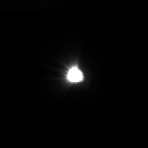
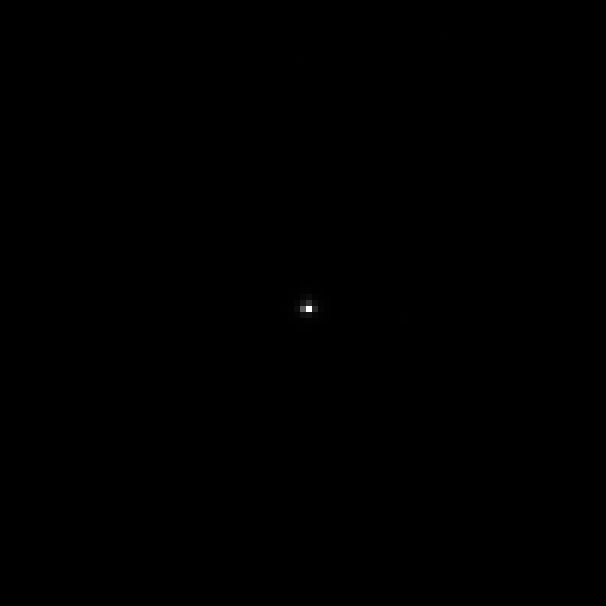
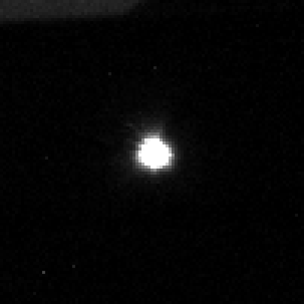
There is not much to write. No reflections or diffuse halos are visible. It makes no difference whether the filter is placed close to the sensor (in a distance of about 35mm) or in the filter holder of the lens (distance to sensor about 120mm).
The following pictures are shots from an artificial star. They are up-scaled by factor 6 without interpolation. Size of each pixel (block in the up-scaled image) is 3.8µm. Brightness is scaled linearly, but the scaling factor on the right side is 1000 times larger.
|
Brightness: ×1 |
Brightness: ×1000 |
| G' |
|
|
| R' |
|
|
| I' |
|
|
Field results
Three test shots are presented on separate pages. Click on the images below to view the results and for detailed descriptions. The pictures where captured with an array of up to three cameras, lenses and filters in parallel (the array was not fully operational at beginning).
[br] The filters perform as expected and show no reflections. These would be very critical, because stars where reduced by a factor of up to 40 in oder to make the faint nebulae visible. That kind of image processing cannot reduce reflections (because they are shifted depending on angle of incidence and distance of the reflecting surfaces) such that they would become very prominent.
Hints and Tricks
Water vapour absorbs infrared radiation (and according to Kirchhoff's law of radiation it also emits in the same wavelengths). The effect is even measurable in visible spectrum: if there is a lot of water vapour in the atmosphere the sky becomes reddish. In infrared the effect even becomes more significant.
On the other hand, sky is blue (due to Rayleigh scattering of the molecules in the atmosphere), even at night. That means, without water vapour sky is darker in (infra)red than in blue. These effects, water vapour and blue sky, more or less compensate each other. Nevertheless, in order to optimize the observation session both issues should be considered if filters are changed during the night('s):
- Use the blue G' filter if the humidity is high or if you shot through a larger amount of water vapour because the object stands low.
Use the infrared I' filter if the moon is shining ar the sun is not far below the horizon.
The test shot where captured in parallel which allows to quantify then sky conditions during the test shots. The average brightness ratio for G':R':I' of the sky measured during the test shots was about 4:4:1 (± 10%). The color factors which compensate the quantum efficiency and transparency (in order or achieve white stars) where about 1:1:2 (± 10%). This leads to a background SNR ratio of 1:1:1, i.e. at same exposure time the SNR (which is mainly determined by the background photon noise) is approximately the same for each filter if the stated color calibration factors (which lead to white stars) are used.
[product sku="baaderfcct"]
- FCCT I für RASA 8" – geeignet für QHY-Kameras mit 77 mm Durchmesser (z.B. QHY 174 / 163 / 183)
- FCCT II für RASA 8" – geeignet für QHY-Kameras mit 90 mm Durchmesser (z.B. QHY 268 / 294)
Lesen Sie hier den ausführlichen Bericht von Christoph Kaltseis zum Baader FCCT und zur QHY163M , QHY268M-PH und QHY294M PRO
Team Baader Planetarium
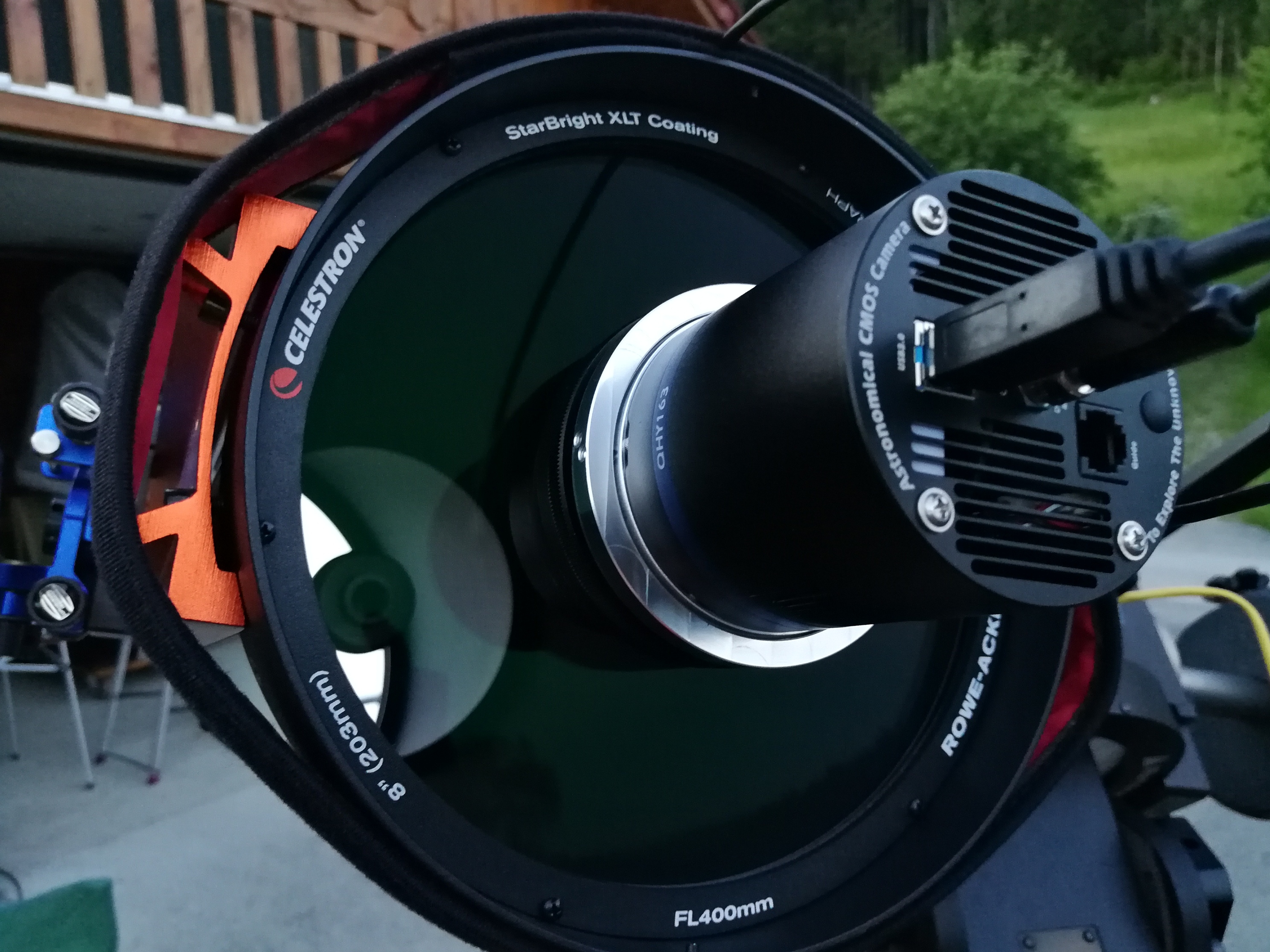
RASA 8, mit dem Prototyp Baader FCCT + QHY163M Kamera
A) BAADER FCCT mit QHY163M:
Nach meinen erstem Eindruck des RASA 8 mit einer ATIK Horizon Farbkamera möchte ich nun meine Erfahrungen mit dem RASA 8 in Sachen Stabilität (Spiegelshifting) sowie zum Baader FCCT I (Filter Changer Camera Tilter) und zur QHY163M zusammenfassen.
Als der allererste Prototyp des FCCT I zur QHY163M ankam und das Wetter am gleichen Abend gut aussah war klar: Jetzt muss es sein – nur gab es für diesen Prototyp noch keine Anleitung...
Der Baader FCCT (Filter Changer & Camera Tilter) macht vom Funktionsumfang (Filterwechseln und gleichzeitig Bildlage perfekt einstellen) einen tollen Eindruck, vor allem verursacht die ganze Mechanik zusammen mit QHY-Kameragehäusen keinerlei Vignettierung. Beim ersten Hinschaun dachte ich, die Montage ist in 5 Min erledigt, aber sooo einfach war es dann doch nicht! Ich wollte ihn einfach in einem Stück an der Kamera montieren. Das ging nicht. Ich musste also zuerst mit einem langem Sechskant-Schraubendreher mit 2mm Schlüsselweite nur die drei kameraseitigen M4 Madenschrauben vorsichtig ca 3,5 Umdrehungen öffnen (wenn man mehr dreht, fallen die Schrauben heraus). Die drei Schrauben in jeweils 120° Abstand voneinander waren zwar schnell gefunden, aber der Außenring der Filterkammer ließ sich dennoch nicht vom Innenteil der Filterkammer abheben. Etwas verhakte sich immer noch.
Was ist da los?
Dann machte es klick bei mir: Ich erinnerte mich an den Ausbau der Schmidtplatte von meinem C14 beim allerersten Mal! Da waren die Celestron-Schrauben auch doppelt - einmal vorn an der Schmidtplatte - und dann noch ganz versteckt an der Seite des Tubus…
Gesucht, gefunden: Auch am FCCT-Außengehäuse fanden sich einander gegenüberliegend noch zwei winzige Schräublein, die die Filterschublade und den Flansch für die QHY-Kamera zur Sicherung fixierten. Dazu fand ich einen winzigen Sechskantschlüssel mit gerade mal 0.9 mm Schlüsselweite. Nachdem ich diese Schräublein soweit herausgedreht hatte, dass auf der Seite wo sie innen vorschauen nichts mehr zu sehen ist, konnte ich den Außenring mit etwas Gewalt von FCCT-Innenteil abziehen (das Teil ist "zu Null" auf Passung gearbeitet - denn seitlich wackeln darf im FCCT gar nichts!). Dieses FCCT-Innenteil musste ich ja anstelle der Ringschwalbe von QHY direkt am Kameragehäuse anschrauben. Das hat ohne Anleitung zunächst auch etwas Hirnschmalz gekostet, denn dazu muss man sich trauen, drei der Schrauben zu entfernen, die den Kameradeckel der QHY-Chipkammer festhalten. Die richtigen Schrauben hatte ich mit etwas Logik schnell gefunden und es lagen auch drei etwas längere Schrauben dabei. Dazu brauchte ich einen beiliegenden 1.5 mm Inbusschlüssel für diese winzigen M2 Schrauben, damit war der kameraseitige Teil des FCCT schnell montiert und die Chipkammer war auch mit drei Originalschrauben einwandfrei dicht geblieben (nur alle sechs Schrauben wollte ich lieber nicht aufmachen). Nun konnte der teleskopseitige Anschluss erfolgen.
Dabei merkte ich, dass ich den FCCT auch auf der anderen Seite zerlegen muss, weil der Celestron-Überwurfring nur montiert werden kann, wenn man den dafür vorgesehenen RASA-Flansch vorher vom FCCT löst und vor der Überwurfmutter anbringt. Daher habe ich die dafür vorgesehenen sechs kleinen Madenschrauben mit dem beiliegenden 1.3 mm Sechskantschlüssen ebenfalls ca drei Umdrehungen geöffnet. Die sechs Schrauben liegen tief im Außenring des FCCT und sind zunächst kaum sichtbar. Da ich die teleskopseitige Hälfte der FCCT-Adapter (Teil 1) noch immer nicht am RASA 8 anbringen konnte, musste ich den eingeklemmten Kunstoffring noch aus der Überwurfmutter "heraushebeln". Ich habe dann die Überwurfmutter zwischen den FCCT-Außenkörper und den Haltering eingelegt und die sechs Schrauben wieder mit dem 1.3 mm Schlüssel fest angezogen. Beim Anschrauben der Überwurfmutter vorn am RASA 8 Bildfeldkorrektor habe ich in einer Ahnung gleich beide der mitgelieferten 0.5 mm dicken Distanzscheiben mit eingelegt – das war schlussendlich auch richtig, um die ideale Fokusposition zu erreichen, denn ich hatte ja vorher auch das Schutzglas vorn aus dem Frontoptik des RASA 8 rausgeschraubt, weil ich keine Vignettierung durch den Filter riskieren wollte. Übrigens - beim Anschrauben der Überwurfmutter war ich ziemlich vorsichtig, um sie nicht zu fest anzuziehen, denn ich hatte schon beim allerersten Versuch - noch ohne FCCT - mit der ATIK festgestellt, dass man bei zu viel Kraft versehentlich die ganze Frontoptik in der Schmidtplatte verdrehen kann.
B) Bilder in LUM mit der QHY163M am RASA 8
Bitte beachten Sie: Der FCCT kann ausschließlich ungefasste Baader-Filter mit den Durchmessern 31 mm / 36 mm und 2" (ohne Fassung) aufnehmen. Sie können die entsprechenden Filterschubladen auf der Produktseite direkt mit bestellen.
-
Filter 1: Luminanz Filter
Der Filter sollte mir bei den ersten Bildern dabei helfen, den RASA 8 mit dem Baader FCCT am Stern zu justieren. Im Vergleich zur Fokusposition der ATIK fiel mir auf, dass ich jetzt mit der QHY den Hauptspiegel am RASA 8 weiter zurück drehen musste. Für mein Empfinden war es viel, da der Stern deutlich unscharf war – 5-6 Umdrehungen war sicher nötig.
Später fand ich den Grund dafür: Der mechanische Backfokus der ATIK beträgt nur 12,5 statt der angegebenen 13mm. Mit den T-2 Fein-Abstimmringe aus Aluminium (0,3 / 0,5 / 1 mm) konnte ich die ATIK damals auf den angegebenen Arbeitsabstand bringen - bei einem so schnellen System kommt es auf die korrekten Abstände an!
Aber beim FCCT waren ja die zwei 0.5 mm dicken Abstimmringe schon im Lieferumfang. Mit der QHY163M funktionierte alles gut. Der erste Alignmentstern war wie schon bei der ATIK wieder Arktur, und wie schon in der ersten Nacht suchte ich einen schwachen Stern in der Nähe der optischen Achse. Gesucht, gefunden und fokussiert: Ich musste ja erst einmal die Abbildung des Systems überprüfen und ggf. justieren. Die Testaufnahme mit der QHY 163M bei Arktur zeigte eine Dejustage links unten im Bild.
Okay!!! Also justieren wir den RASA 8 f2 am Stern. Dazu fuhr ich Wega an (mein zweiter Alignment-Stern), die am Osthimmel stand. Hier hatte ich einen langen Weg bis zum Meridian, den ich aber nicht ganz ausnutzen wollte. Die Justage war wie bei meinem bereits vertrauten RASA 11. ZUERST muss die Bildmitte exakt im Fokus sein, dann erst geht es bei der schlechtesten Bildecke weiter. Dort startet die Justage. Mit Erfahrung und Glück hatte ich gleich die richtige Ecke erwischt!
Mit den sechs M4 Madenschrauben am FCCT (je 1 für Druck und Zug an jeder der drei um 120° versetzten Positionen) und dem ewig langen 2 mm Sechskant-Schlüssel heißt es nun, die Sterne durch sanftes Drehen an einer Schraube deutlich kleiner und zugleich runder zu bekommen (dabei vermisste ich meine Bathinov-Maske). Danach wieder ein Bild mit gleicher Belichtungszeit und LUM machen - am RASA reichen schon 5 Sekunden Belichtungszeit um gut zu erkennen, was sich getan hat. Dann geht es Schritt um Schritt, bis das Feld beim Chip der QHY163M am Ende perfekt rund bis in die Bildecken wird.
Zwischen den Schritten darf man nicht vergessen, immer wieder einmal neu zu Fokussieren. Vor allem: mit Ruhe und Sorgfalt arbeiten, am Ende wird man dafür belohnt!
Mein Tipp: Sagen Sie sich laut vor, was Sie gerade machen, welche Schraube und welche Richtung. Merken Sie sich die Ausrichtung der Schrauben zum Feld der Kamera um zu sehen, wie welche Schraube wirkt. Ich verspreche Ihnen, das macht es einfacher… auch wenn meine Frau mich in einer kleinen Kaffeepause fragte, mit wem ich eigentlich sprechen würde.
Nach einiger Zeit war die Justage fertig, und alle Sterne waren rund bis in die Bildecken! Also richtete ich den RASA 8 mit der QHY163M und Lum Filter (bei nur -10°C eingestellter Temperaturdifferenz) auf NGC7000 und den Pelikan Nebel. Ich richtete den Kamerachip so aus, dass Norden oben war und die RA + DEC Achsen den Kanten synchron waren. Also noch einmal fokussieren, und los geht’s wie gehabt.
Dann belichtete ich bei NUR Gain 10 (von über 500!) und Offset 25 gerade einmal 180 Sekunden, und es war IRRE!
Die Dynamik mit der enormen Tiefe war grandios!
Ich habe dann eine Serie bei -10°C gestartet, 180s Lum, Bin1, Download: Fast alles lief perfekt, und 30 Minuten später waren die Daten „im Kasten“.
Der RASA 8 mit der QHY163 und dem Baader FCCT ist der nächste Schritt in der Astrofotografie: Die Bilder machen einfach nur Spaß!
Der RASA 8 Hauptspiegel machte !keine! Verkippung, wenn er am Objekt fokussiert wird.
Der FCCT hat auch nach drei Nächten seine Justage exakt gehalten ohne sich zu verändern, die Abbildung im Feld ist TOP! Ich habe dem RASA 8 mit der QHY auf meiner EQ 8 Platte hin und her geschoben, das System ist stabil!
IC 1396, Celestron RASA 8 mit Baader FCCT + Baader UNB f2 Highspeed Filter (3.5nm / OIII (4nm) / SII (4nm), BLZ total 150min, crop @ 85% size, © Copyright Christoph Kaltseis 2021
C) Ein paar Worte zur QHY163M und was Sie beachten sollten
Ich habe die Kamera anfangs nicht ohne Probleme zum Laufen bekommen. Bildfehler, lange Download Zeiten, keine Bilder, Abstürze von MaxIm DL, und mit der original QHY Software das gleiche wie in MaxIm DL…
In der ersten Nacht mit dem RASA 8 musste ich den Treiber der Kamera und den ASCOM-Treiber für MaxIm DL (direkt von der QHY Webseite) neu installieren. Danach ging es erst einmal ohne Fehler, das war aber nicht die Lösung des Problems. Ich verwendete einen PC mit Windows 10, i7, SSD, ASCOM 6.4 SP1 und USB 3.0… aber dieser Rechner wurde von einer Windows 7 Installation über Windows 8.1 auf Windows 10 upgedated. Der Gerätemanager zeigte alles korrekt an, das war es aber nicht!
In der nächsten Nacht wollte ich die H-Alpha-Aufnahme nachholen, aber es gab nur Stress – die Kamera lief nie wirklich ohne Problem. Schließlich sorgte das Wetter für ein Ende der Tests.
DANN nahm ich einen anderen Windows 10 Rechner mit ASCOM 6.4 SP1 und USB 3 (meine Wacom MSP16). Auf dem Rechner war von Anfang an nur Windows 10 installiert, ohne Updates von früheren Versionen. Ich lud die Treiber wie auf der QHY Seite bei der QHY163M genannt herunter, installierte sie (System und ASCOM zur QHY163M) und machte den Neustart des Computers.
Nun die Kamera eingeschaltet, danach über USB 3.0 angesteckt.
Jetzt kam der große Unterschied und der Hinweis, dass es funktioniert: Der Treiber wurde geladen und ich musste eine Verifizierung des Treibers von Hersteller in Windows 10 mit O.K. bestätigen. Das war neu! Zuvor erkannte der Computer zwar die Kamera, aber es war nicht korrekt, obwohl der Gerätemanager sagte: Alles funktioniert einwandfrei! Auch das akustische Signal war zuvor schon ertönt, mit dem neue USB-Gerät erkannt werden.
Das liegt daran, dass unter Windows 7, 8 und 8.1 die USB-Anschlüsse anders gehandelt wurden als unter Windows 10. Da musste ich auch erst einmal dahinter kommen.
Wenn ich nun die Kamera in MaxIm DL starte, läuft sie OHNE einen Fehler.
Noch ein zweiter Hinweis: Der ASCOM-Treiber in MaxIm DL merkt sich die Werte für Gain und Offset. Wenn die Werte nicht korrekt sind, sind Gain 174 und Offset 77 ein guter Startwert.
Und zu guter Letzt: Vertrauen Sie weder den Angaben zur Fokuslage des Teleskopherstellers noch den Backfokus-Angaben Ihrer Kamera! Leichte Abweichungen können - bei jedem Teleskop unterschiedlich - durchaus vorkommen. Man muss evtl mit den 0.5 mm Distanzringern experimentieren.
M16, RASA 8 f/2 mit Baader FCCT + f2 Highspeed Filter (H-alpha, SII, OIII),; 12x Ha, 12x O3, 14x S2 - 300 seconds; Kamera: QHY163M, Gain 50, Offset 25 @ -15°, Software: Maxim DL, Pixinsight & Adobe Photoshop CC 2019, Gesamtbelichtungszeit: 190min, Pixel Skala: 1,95“ mit der QHY163M, © Copyright Christoph Kaltseis 2019
IC1318, Belichtet wurde 205 min und die Palette SHO ist als RGB gesetzt worden. (300sec Subs). Keine SCHÄRFUNG! Der Reflex um Sadr (2,2mag) ist abgeschwächt, und tief verborgen ist ein dritter Reflexring. Aber 300s bei f2 entsprechen 600s bei f2.8 und 1200s bei f4! © Copyright Christoph Kaltseis 2019
[br]
Baader FCCT für die QHY294M PRO und QHY268M-PH Kamera
Nachdem der Baader FCCT für weitere QHY-Kameras mit 90 mm Durchmesser entwickelt wurde, konnte ich diese modifizierte FCCT-Ausführung an meinen RASA 8" gleich ausprobieren. Der Baader FCCT ermöglichte es (mit der gleichen Vorgehensweise wie beim FCCT I), die QHY294 und sogar die QHY268 perfekt auf die optische Achse des RASA einzustellen.
[br]
Celestron RASA 8, QHY 294C Baader FCCT mit Baader Neodymium Filter / RGB 17x120sec = 34min bei 400mm
[br]
Ich werde auf jeden Fall noch weiter mit dem RASA 8 experimentieren!
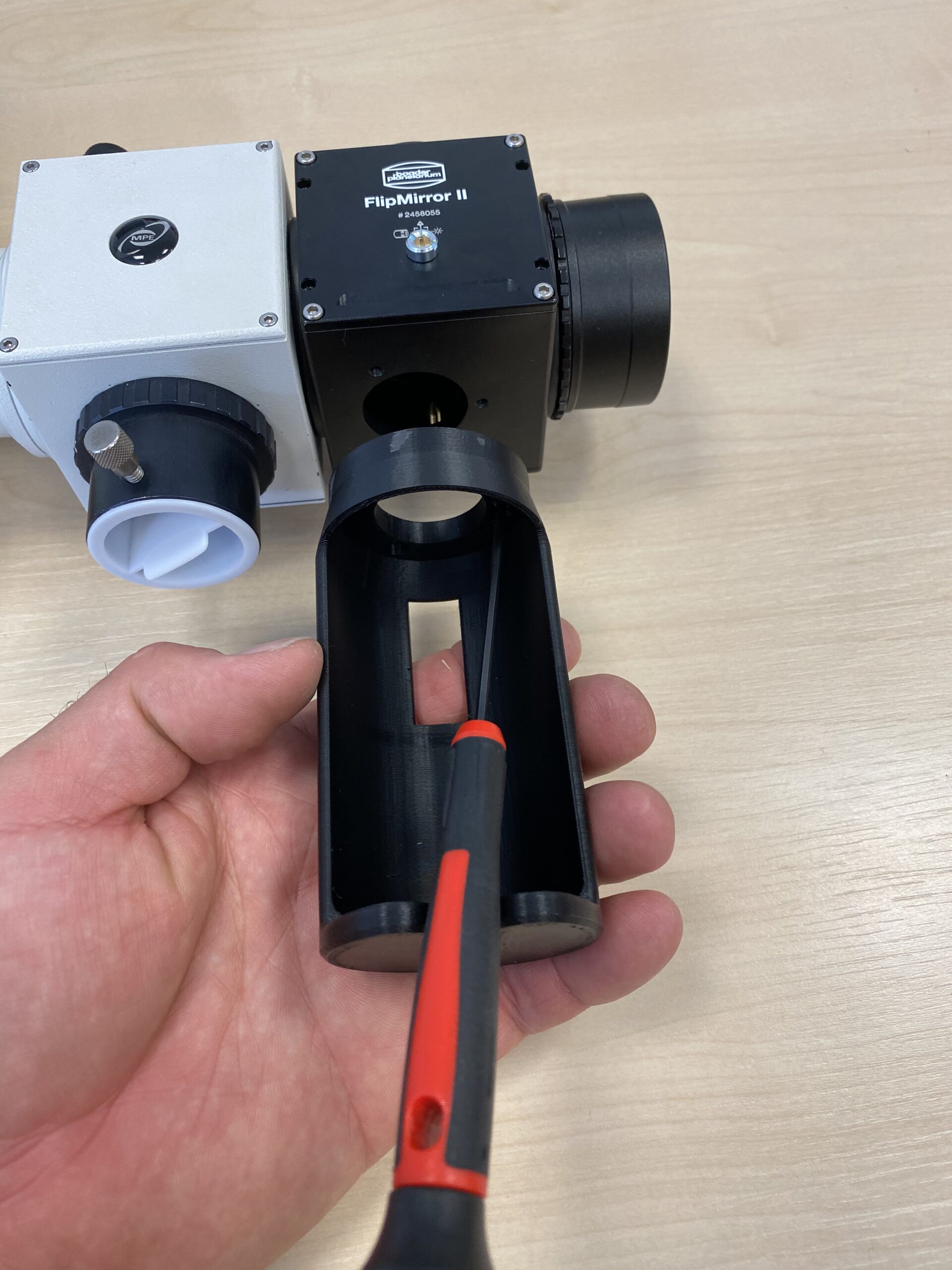
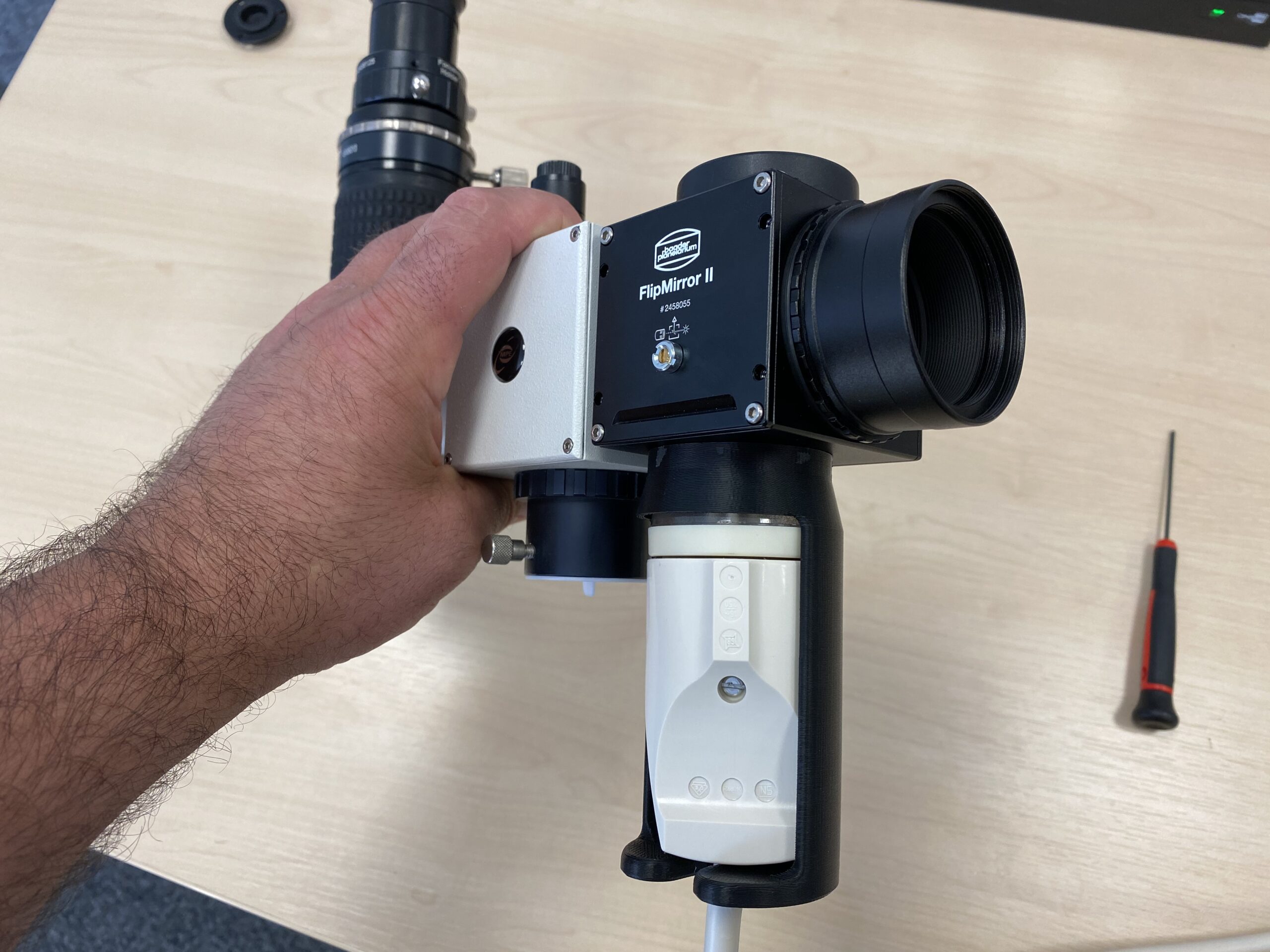
Free Download: 3d-printed FlipMirror II Mirror Holder
Update: We are pleased that the [product sku="2458055"] is so well received and inspires some customers to dream about what else would be possible. Since we ourselves cannot realize all the different constellations from partially transparent to dichroic mirrors, we have decided to publish the mirror holders that we install in the FlipMirror II. This way, our customers and users can 3D print the holders themselves and then try out any mirror type and shape. We are looking forward to your results and experience reports!
Below is the download link (which will only work when you're logged in). Please also note the information below about the Creative Commons License.
The file is optimized for printers according to the FDM procedure. Ideal would be a heated pressure bed. Material with little warping or heated space. Preferably PLA. As a primer we recommend Bluetape.
[br]
{{block type="mageworx_downloads/link" id=1784 title=""}}
[br]
Free Download: 3d-printed Flip-Mirror adapter for DADOS calibration lamp
The [product sku="2458055"] lets you the possibility to use a telescope visually and at the same time leave an instrument like a camera or a spectrograph permanently installed. As a third, lower port, it therefore offers a connection option either for an off-axis/autoguider via the [product sku="2956951"] or for a dedicated calibration lamp. To guide the light of the calibration lamp to the sensor, the FlipMirror is also mirrored on the back side.
Our popular [product sku="2458550"] can be operated with the FlipMirror, too to easily switch between visual observation/centering or setting the object and its spectroscopic measurement.
The optional [product sku="2458590"] is designed to be plugged into the 2" nosepieces of the DADOS to take a comparison spectrum when the DADOS is not connected to the telescope.
When the Schülerforschungszentrum Lörrach with the observatory Gersbach approached us with the idea to connect the calibration lamp of the DADOS to the BFM-II, however, we did not yet have a suitable adapter on offer. 3D printing offered a quick solution: An adapter was quickly constructed that could be screwed onto the FlipMirror. The neon calibration lamp is then inserted into the adapter in a light-tight manner.[br]
[br]The adapter has already proven itself in use, and we are happy to provide the print file to the spectroscopy community for free! We offer the STL files for free download. All you have to do is log in or register on our website with your customer account.
Below is the download link (which will only work when you're logged in). Please also note the information below about the Creative Commons License.
The file is optimized for printers according to the FDM procedure. Ideal would be a heated pressure bed. Material with little warping or heated space. Preferably PLA. As a primer we recommend Bluetape.[br]
[br]
{{block type="mageworx_downloads/link" id=1759 title=""}}
[br]
Please note
Do you want to stay informed about new products, special offers (such as this download file) and other important information? Than we recommend to subscribe to our newsletter.
- Unfortunately we do not have the capacity to produce these adapters in large numbers in our production. In turn, producing individual pieces would be too expensive. We therefore regret that we have to reject requests to print this adapters in our facilities.
- If you have a 3D printer, you can print the .STL file directly
- If you do not have a 3D printer and are still interested in this adapter, you can contact a 3D printer service. Numerous providers can be found online - or maybe you already have a 3D printing company you trust?
- If you have problems or questions about the file, you can of course contact us at any time
Baader M68 adapter with M68-Tilter + UFC for the QHY600M camera
The Baader M68 is a system that fulfils many wishes in an elegant way and with high stability. All distances can be set precisely, and with the [product sku="2458170"] an ingenious extension has been added to the system.
But before talking about the tilter, let me tell you how I came to this system. When I was testing the prototype of the [product sku="baaderfcct"] for the RASA 8, I wished that the connection and collimation possibilities for the C14 were just as sophisticated. I have acquired enough experience so that I can "read" the image of the C14 so well that I know whether I am really seeing a tilt or just a problem with the distance. Of course, this led to the desire to use a tilter to adjust the field perfectly to the camera sensor.
I mentioned this idea in passing once during a conversation with the Baader company, and we discussed what functions would have to be incorporated so that imaging with the C14 EdgeHD could be optimised as easily and smoothly as with the RASA 8 and the FCCT. After all, we are talking about a large Schmidt-Cassegrain telescope, and that should be capable of 36.3MP full-frame images – or even more?
The fact that I kept coming close to ma desired image quality, but couldn't reach what I would have liked, may also be due to the fact that I use five different cameras on the C14, and each one is a little bit different, with small subtle differences in sensor position and distance (back focus). It has been clear to me for some time that the backfocus on the EdgeHD has to be met with a tolerance of 0.2mm! And the images get even better when the error is smaller.
Well, and now there is this little "M68 filter wonder", and the handling is very good! But that doesn't change the fact that the optics really have to be very well collimated! Because, of course, it is not possible for a tilter to solve every problem. But if everything fits, then even 61 megapixels can be used on the C14 EHD, with round stars from one corner of the image field to the other.
And how do you get the most out of a 61 megapixels camera attached to the C14EdgeHD? My first tip for proper preparation is to buy a Celestron EdgeHD directly from Baader, because they know a significant tad more about it - I can't write why now, but I know it.
When preparing the optics and adjusting the accessories to match the backfocus, the distance for the M68 system with the tilter unit has to be calculated 0.2 - 0.3mm shorter than the ideal working distance of 146.05mm of C9.25, C11 and C14 EHD telescopes! In the white paper on the EdgeHD series you can see what shape the stars have over the field of a full-frame camera when the distances are correct.
Tip: If you manage to install the M68 tilter in the system so that the screws on the tilter meet the image diagonals and the left / right or top / bottom corners, it is even easier to adjust the system perfectly!
Baader M68 adapter + M68-Tilter + Nikon D810A
The camera adapter with the M68 tilter is then attached to the EdgeHD and the star must be focussed with an accuracy of 99.9%. Only then the optics are in "best shape" and photography with up to 61.1MP is feasible.
Then I attach the Nikon D810A and place the tilter into the adaptation in such a way that even if I change the camera, the tilter remains in the system just as it was when I made the adjustment!
When everything is really in place, I collimate the EdgeHD with the help of that star so that the secondary mirror is perfectly orientated to the main mirror. Important: Do not be satisfied with 99% perfection, but gor for 99.9%! This can be done at any moon phase with really GOOD seeing. Then it is the time for the tilter.[br]
What must be done and be taken care of?
Der Baader M68-Tilter on the Celestron C14 EdgeHD. Checking the image in the field with a full frame camera and 36.3MP.
I use a sturdy dew cap instead of a flexible one that fits exactly on the two 3" rails on the C14. Thus it is not "crooked" - I checked that! To see the field tilt better, I use a Bathinov mask. I put this on the dew cap (flat and not sticking out) and adjust the focus, then I take a picture of about 30 seconds so that I can check the field. (The tracking must be TOP, because otherwise you will try to adjust for this error, too!)
Now I can focus on the worst corner of the image where the Bahtinov mask shows the greatest deviation. I move the star to the corner of the image and change the focus NOT AT ALL! For this, it is ideal if I have previously aligned the M68 Tilter with the axes of the sensor (as far as possible), because then I can find the right adjustment screw with simple trial and error - i.e. by turning a screw and seeing what happens!
If the image changes in such a way that the middle line of the Bathinov pattern moves towards or away from the centre, then it is the right screw. If nothing happens, then the selected screw is not effective in that corner of the image. Yes, this method requires some time, and I had to work out the practice first.
Tip: As a further aid, the Bathinov mask can be rotated by 90° to see the deviation clearly, if necessary.
Write everything down, note every "turn" of a screw and don't forget: If you can assign a screw to a corner of the picture, make a sketch of it. This sketch shows the position of the M68 tilter in the M68 system. Give each screw a NUMBER and then enter this number in a second sketch, which should represent the sensor. Then you know, screw 1 changes this,... Then you have completed this exercise!
After every second screw that was used for the adjustment, the following applies: Place the star exactly in the centre again and focus! Because the closer you get to perfection, the smaller the deviation of the centre line becomes! Therefore, the focus must be perfect, then you will always recognise the one corner of the picture that still needs to be corrected. This sequence is interrupted by test shots, so expose for 30 seconds and look for the worst picture corner! The whole thing ends at the point where all corners of the image are at 99% perfection.
If the stars in all the image corners are slightly elongated (egg-shaped towards the outside!) because we used a 0.2-0.3mm shorter backfocus to allow for tilting, then the distance must now be lengthened by 0.2 - 0.3mm. For this purpose, Baader M68 offers M68 Fine-Adjustment rings made of aluminium (0,3 / 0,5 / 1 mm). These are inserted quickly. Then: Focus again and check the field, but this time without the Bathinov mask! In case there is a deviation, simply adjust again, the sketches should make this easier!
Tip: Check the settings of the camera or camera driver if there is an automated flip or a rotation when downloading to the computer – if the images are automatically rotated, the assignment of the screws will not be easier! Depending on this, you can deactivate this automatic image rotation!
Conclusions:
This way, the whole system can be adjusted; if the M68 tilter is removed together with the camera, the adjustment is retained even when the camera is replaced with another one. With the tilter, the M68 system now not only offers the possibility to mount even heavy accessories stable and without vignetting, but is extended by the possibility of simple and stable adjustment.
Iris Nebula NGC 7023 at 3910mm with Nikon D810A

QHY 30mm aperture, 130mm focal length [product sku="1932051"]
miniGuideScope with dew shield, objective cover, mount and aluminium storage box. The QHY camera is not included.
Guiding is essential for taking long exposure images of such celestial objects. Long gone are the days when your guidescope was a telescope that would be similar in focal length as your imaging scope and you would guide by looking at a star through a high power cross-hair eyepiece making rapid adjustments manually! Nowadays with high resolution, sensitive image sensors and advanced software imaging algorithms that allow sub pixel star centroiding, smaller aperture shorter focal length telescopes can be used for guiding. If you want a lightweight and compact guidescope to complement your imaging setup QHYCCD's miniGuideScope (mGS) could be just for you. The mGS is available as OTA only and also as OTA with mounting bracket.
The telescope: size and weight
The mGS comes in a sturdy aluminium container with foam inserts to keep the telescope safe during transport or storage. The outside of the telescope body and its finderscope dovetail mount are finished in an attractive stylish matt silver finish. The interior of the telescope is painted matt black to minimise internal reflections.
The mGS being handheld showing how compact the unit is.
mGS and mount weigh less than 220g
The scope itself is 31.6mm diameter (similar to a 1.25" eyepiece barrel) and is small in length at only ~115mm with the focuser fully inward. With a QHY5P-II-M camera attached and focussed ready for guiding (as shown) the length of the overall scope and camera combination was only 170mm (without dew shield). The OTA itself weighs a mere 118g without dew shield and camera attached. With its mini-dovetail mounting bracket the complete unit is still lightweight at just ~220g, and with a small guidecamera such as QHY5-II series attached ~260g. It's small, compact and light weight form factor means that it is ideal for using on set ups where (additional) weight of a larger guidescope and associated accessories may be an issue. Furthermore, the mGS is ideal for long exposure astrophotography with small (ultra-)portable tracking platforms (see photo for an example set up).
Camera attachment:
On the rear of the telescope there is a male CS screw thread for direct camera attachment and many guide cameras use this type of mount. The guidescope is compatible with the current QHY Series II and Series III cameras such as the QHY5L-II-M, QHY5-III-178 and QHY5-III-290 as well as a range of other cameras using the Cs lens thread attachment. This mGS is also a great match for [product sku="1485001"] which works best with guidescopes with focal lengths of 100mm-150mm. In this case, the black threaded adapter at the end of the mGS must be replaced with [product sku="1485010"]. For those doing astrophotography using a camera tracking platform and a DSLR/Mirrorless camera, the combination of the small lightweight mGS and the "without-a-pc operation" of the StarAid Revolution for guiding and camera control contribute towards a truly portable grab-and-go astroimaging system.
Example set up showing a QHY mGS mounted on a portable camera tracking platform for DSLR wide field imaging
Objective end and focus:
Moving towards the objective end of the telescope, the mGS uses a high quality 30mm aperture doublet achromat lens with a focal length of 130mm (f/4.3) and features a broadband anti-reflective coating. Focusing is achieved with a simple screw-twist of the end barrel of the OTA and a single focus locking screw allows you to lock the focus position. The telescope can focus from 1.5m - ∞ and focus position indicator markings assists in helping to achieve focus and also refocus positioning if the camera has been removed or changed. A small aluminium screw-on dew shield completes the objective end of the mGS.
Mounting:
The mGS mounting bracket features two tube rings each with a plastic tipped locking screw to secure the OTA in place. The inside diameter of the tube rings are just slightly larger that the guidescope tube so no positional adjustment of the guidescope can be done. However the telescope's large field of view means this is not an issue as as suitable guidestar can be located in just about any part of the night sky. The rings are attached to a mini dovetail base that allow it to be attached to a wide range of telescopes that feature this common type of finderscope/guidescope shoe-bracket attachment. For telescopes that either require such a shoe or if you need an additional bracket, we offer our [product sku="2457000"], which can be attached to most telescopes with tubes 130-400mm in diameter, and features two locking screws for secure guidescope attachment. The mGS base also features a standard 1/4" UNC tripod threaded hole so that the mGS can be attached to e.g. telescope tube rings.
Base of the mGS bracket showing the 1/4" UNC tripod thread
Field of view:
With the mGS's short 130mm focal length, what field of view will you get on the sky? That will of course depend on the camera and its sensor being used.
However, to give you some idea of FOV, below we present a table that lists a few of the current popular guidecameras along with the sensor pixel array, pixel size and the resulting pixel scale and field of view in degrees.
| Camera |
Sensor Array
(pixels) |
Pixel Size
(µm) |
Image Scale
(" / pixel) |
F.O.V
(deg) |
| QHY 5-III 174M / ASI174 |
1920x1200 |
5.86 x 5.86 |
9.30 x 9.30 |
4.96 x 3.10 |
| QHY 5-III 178M |
3072x2048 |
2.40 x 2.40 |
3.81 x 3.81 |
3.25 x 2.17 |
| QHY 5-III 290 / ASI290 / StarAid Revolution |
1920x1080 |
2.90 x 2.90 |
4.60 x 4.60 |
2.45 x 1.38 |
Below, we have shown these camera F.O.V's superimposed on a celestial image of Messier 31 (Andromeda Galaxy) to give you a more "visual-orientated view".
mGS field of view with a selection of popular sized sensors used in guide cameras.
In summary, [product sku="1932051"] is a high quality, small and lightweight guidescope that is easy to set up and use and can be used with many imaging setups. With it, and a compatible camera, it can help you obtain long exposure images of celestial deep sky objects.
QHYCCD also design and manufacture a wide range of high quality, excellent performance and reliable cooled CMOS and CCD astronomical imaging cameras ranging from entry level up to professional astronomy grade that are used in research programs. To complement their cameras they also produce dedicated accessories including filter wheels, off-axis guiders and adaptor kits. You can find out more about QHYCCD and their product catalog here.


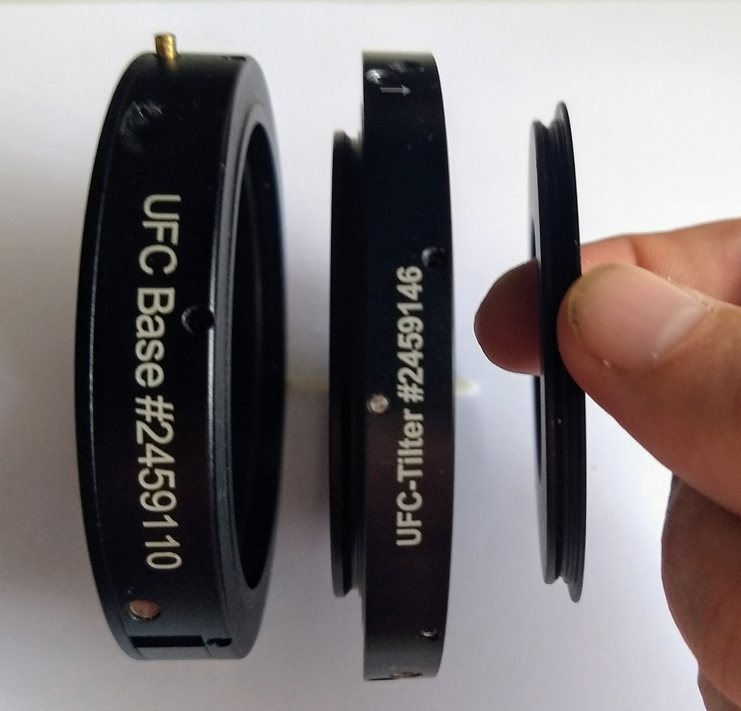

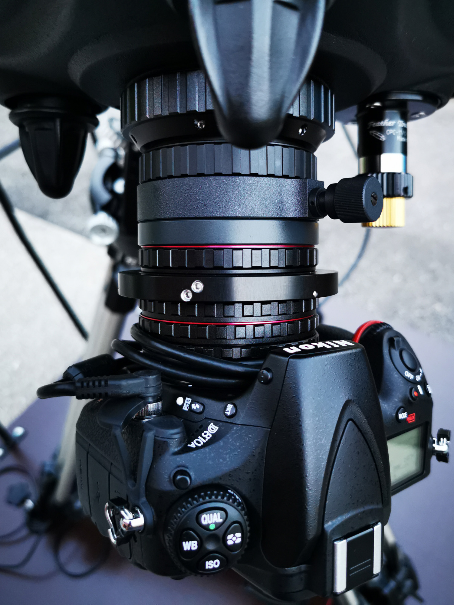

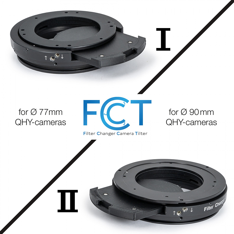
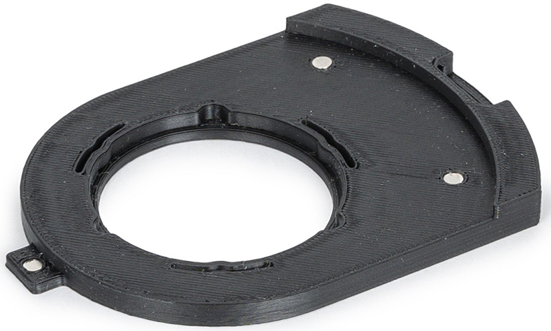
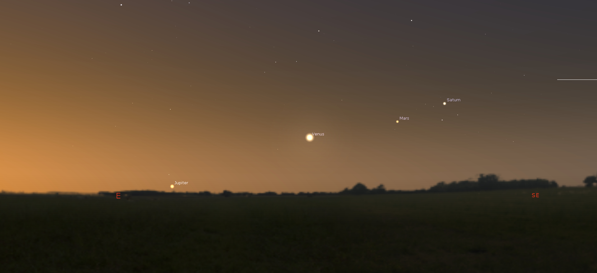
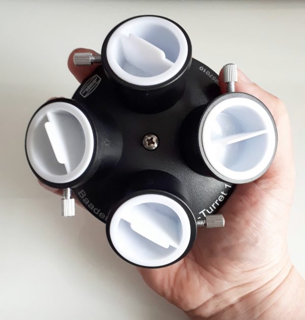
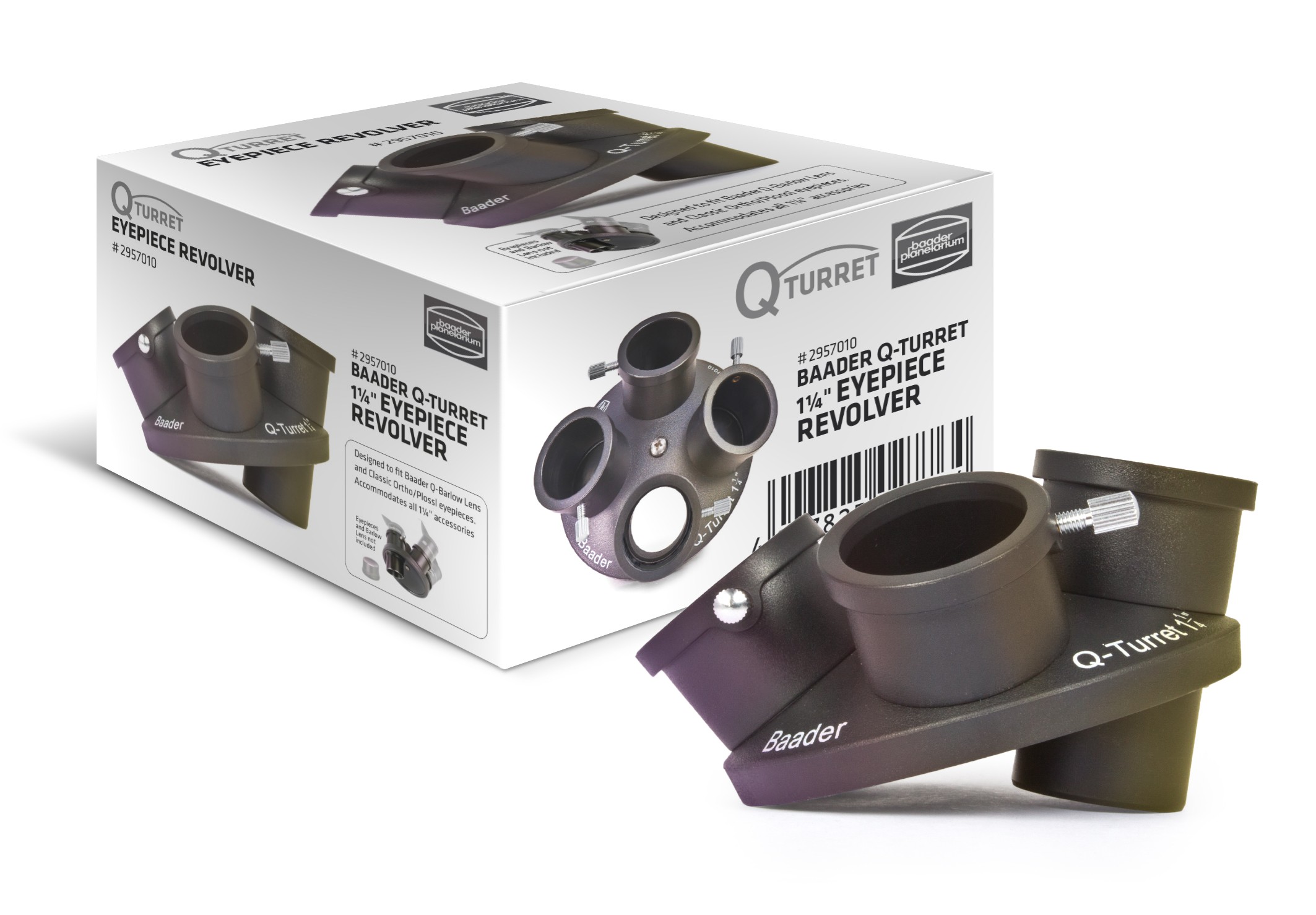
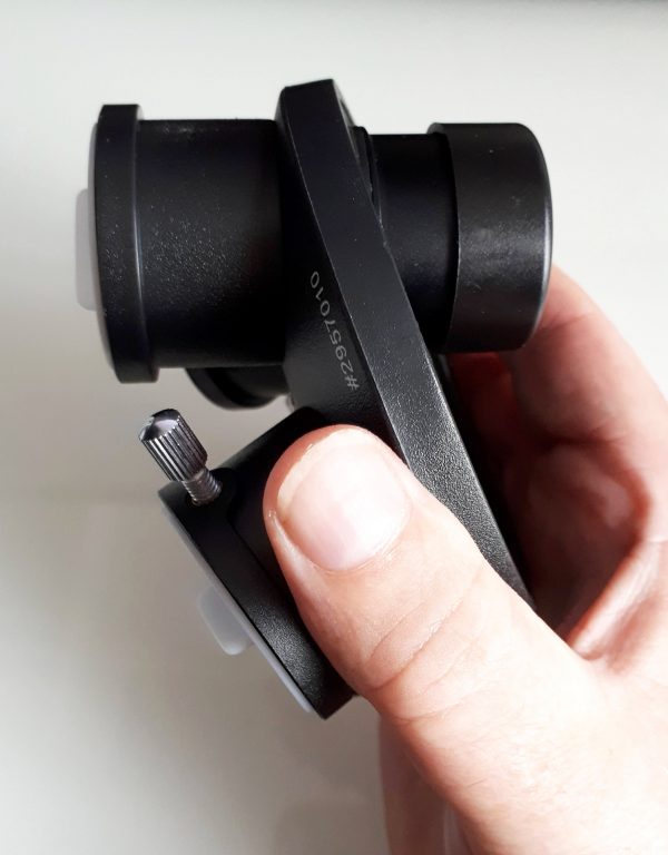


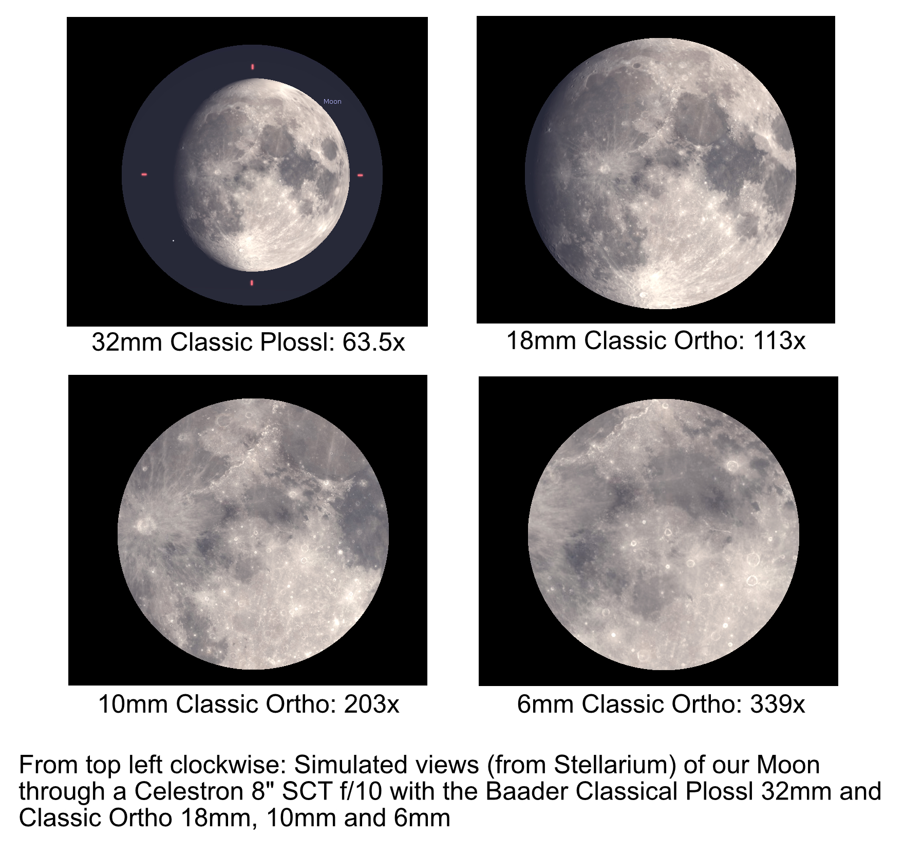
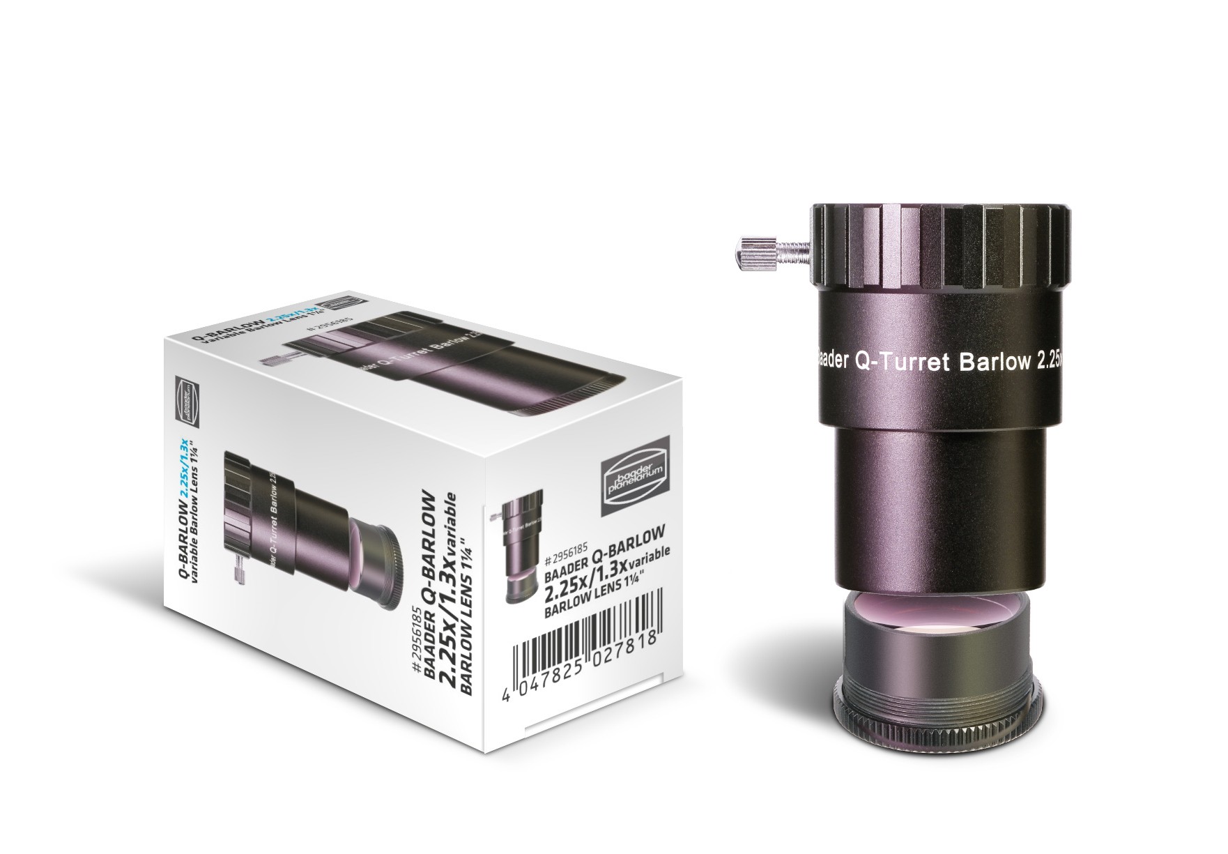


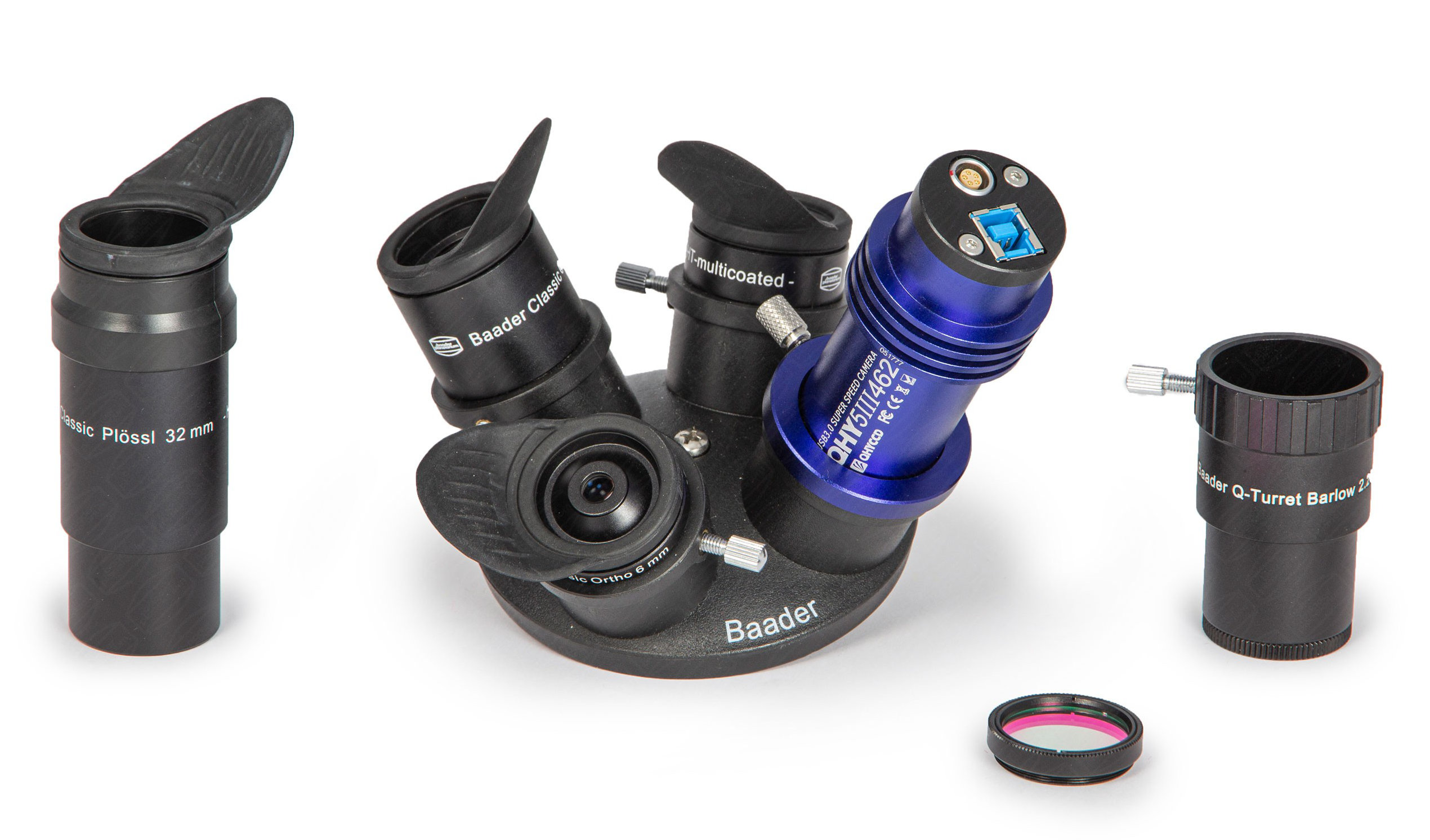


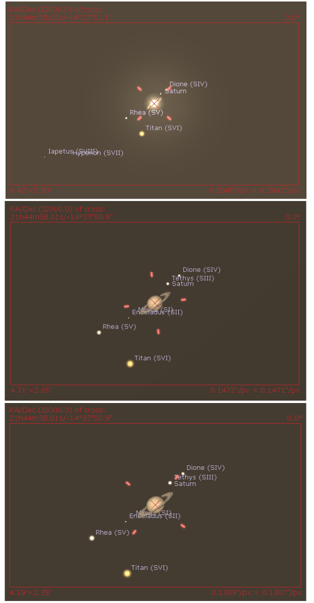


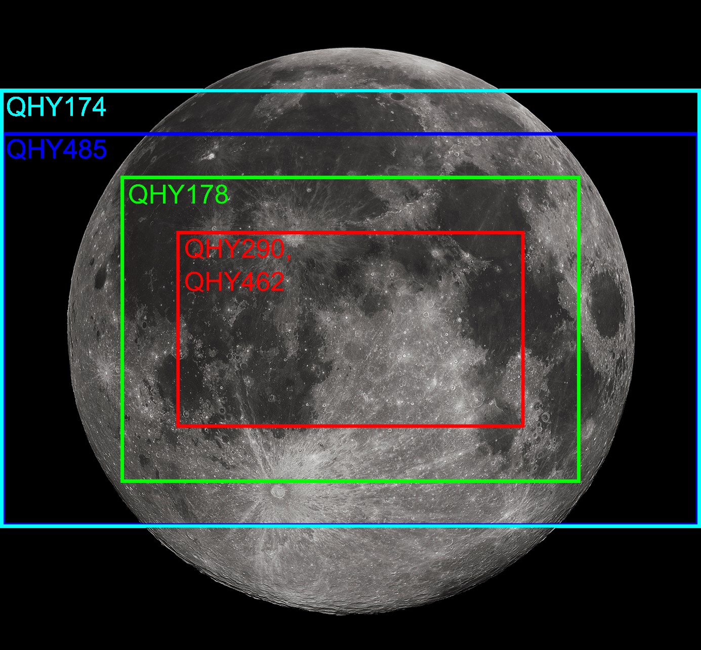


 Intro
Intro Iris Nebula
 Pleiades
 LDN 1495